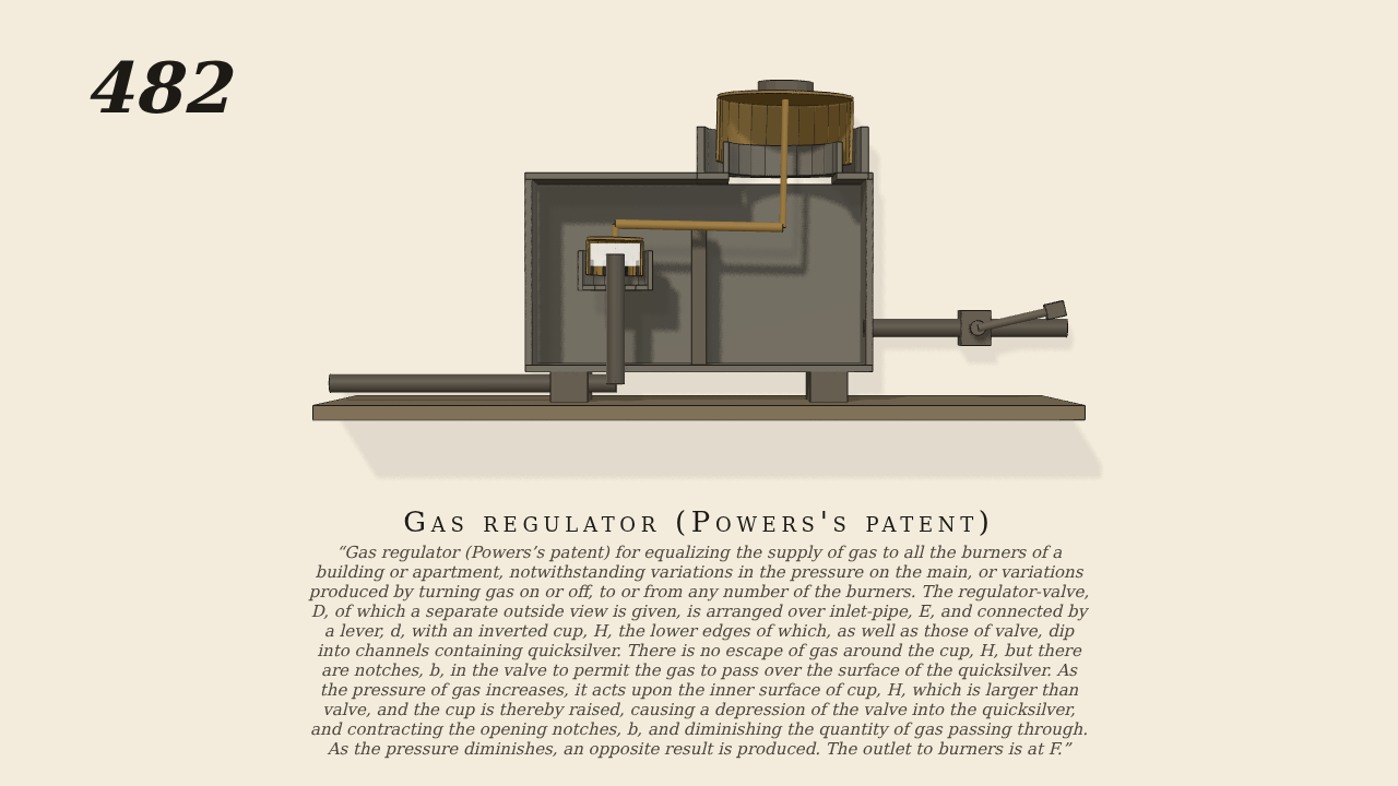
Gas regulator (Powers's patent)
Gas regulator (Powers’s patent) for equalizing the supply of gas to all the burners of a building or apartment, notwithstanding variations in the pressure on the main, or variations produced by turning gas on or off, to or from any number of the burners. The regulator-valve, D, of which a separate outside view is given, is arranged over inlet-pipe, E, and connected by a lever, d, with an inverted cup, H, the lower edges of which, as well as those of valve, dip into channels containing quicksilver. There is no escape of gas around the cup, H, but there are notches, b, in the valve to permit the gas to pass over the surface of the quicksilver. As the pressure of gas increases, it acts upon the inner surface of cup, H, which is larger than valve, and the cup is thereby raised, causing a depression of the valve into the quicksilver, and contracting the opening notches, b, and diminishing the quantity of gas passing through. As the pressure diminishes, an opposite result is produced. The outlet to burners is at F.
Only the input is driven; every other part of this model moves by physics (MuJoCo), and its ratios are measured. Run it live, change its parameters, or switch the friction off to see the output stop.
- Modelled as
- Seen from in front, the case cut away in half section, gravity on. A lever d on a pivot carries the regulator valve D, over the inlet pipe E, at one end, and the inverted cup H (larger than the valve, with a weight on its crown) at the other. The main's pressure is the input; the inlet and the case are lumped gas vessels. Gas passes through notches b in the valve, and the notches' opening follows the valve's travel. The case's pressure acts up inside H and on the valve, through pistons on the lever. Gas goes out at F to the burners through a cock that is swung slowly open and shut.
- Measured
- As the burners' draw changes, the lever tips between about −0.08 and +0.02 rad, closing and opening the notches. This holds the case at 224–264 Pa while the flow varies from 0.3 to 1.9 g/s. The gas is drawn and shaded by its pressure. The motion gate passes.
- Notes
- Grade B. The quicksilver seals are not drawn: they are modelled as no escape around H. The gate's WARN that the mechanism crosses the title comes from the base's shadow near the long caption. The no-water WARN is expected for a gas movement.
Film (MP4) · Still (PNG) · Spec (YAML) · Model (MJCF)