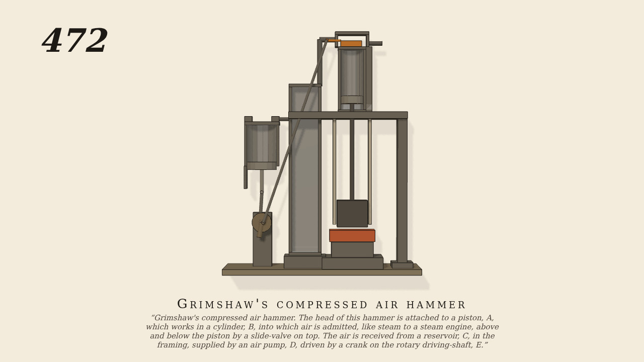
Grimshaw's compressed air hammer
Grimshaw’s compressed air hammer. The head of this hammer is attached to a piston, A, which works in a cylinder, B, into which air is admitted—like steam to a steam engine—above and below the piston by a slide-valve on top. The air is received from a reservoir, C, in the framing, supplied by an air pump, D, driven by a crank on the rotary driving-shaft, E.
Only the input is driven; every other part of this model moves by physics (MuJoCo), and its ratios are measured. Run it live, change its parameters, or switch the friction off to see the output stop.
- Modelled as
- Seen from in front, gravity on. The crank on the driving-shaft E turns at 120 rpm (the only drive). It works the air-pump D, which draws air through its suction valve and drives it through its delivery valve into the reservoir C in the frame's column, and by an eccentric and a long rod it works the slide-valve on top of the cylinder B. The valve lets the reservoir's air in over or under the piston A, as a slide-valve does steam in an engine, and lets the other side out. The pump, the reservoir and the air over and under the piston are lumped gas vessels (src/fluid/vessels.c), each drawn and shaded by its pressure (add-steam-drawing). The hammer head is on the piston's rod.
- Measured
- The hammer lifts from the work to about 9 cm and falls on it once a revolution; the reservoir sits at about 20 to 29 kPa gauge. Gate: pytest 2 passed, lint 0 FAIL, motion gate pass.
- Notes
- Grade B. One WARN: no water visible, right for an air hammer. Isothermal lumped air; the crank needs a heavy crank (flywheel mass) for a steady speed.
Film (MP4) · Still (PNG) · Spec (YAML) · Model (MJCF)