Flexible water main, plan and section
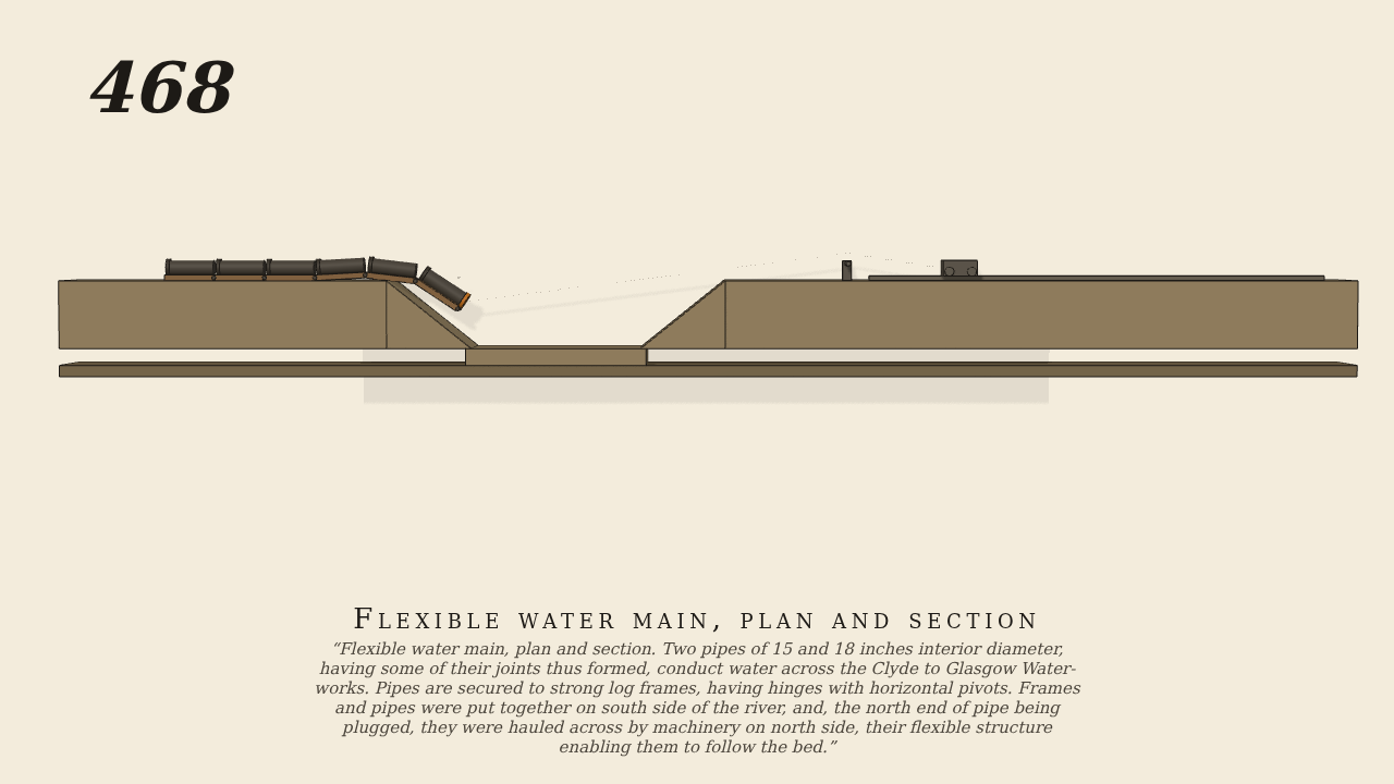
Flexible water main, plan and section. Two pipes of 15 and 18 inches interior diameter, having some of their joints thus formed, conduct water across the Clyde to Glasgow Water-works. Pipes are secured to strong log frames, having hinges with horizontal pivots. Frames and pipes were put together on south side of the river, and, the north end of pipe being plugged, they were hauled across by machinery on north side, their flexible structure enabling them to follow the bed.
Only the input is driven; every other part of this model moves by physics (MuJoCo), and its ratios are measured. Run it live, change its parameters, or switch the friction off to see the output stop.
- Modelled as
- Section seen from upstream, south on the left. Six hinged log frames, each carrying its length of pipe, are put together on the south bank; a rope from the leading frame passes over a sheave on the north bank to a carriage drawn at a steady 6 cm/s (the only drive, the hauling machinery). The frames hinge on horizontal pivots and rest by their weight on the banks and bed, so the chain bends down the south bank, along the bed and up the north bank.
- Measured
- The chain follows the bed: the leading frame ends about 75 cm along (allowed 45 to 90), on the north bank, with the frames bent to the bank slopes in turn. Deepest contact about 0.01 mm. Gate: pytest passed, lint 0 FAIL, motion gate pass, no flags.
- Notes
- Grade B. The river's water is not modelled (it does nothing in the haul but buoy the pipe, which Brown does not describe), so this is a mechanism without water; the pipe is drawn as a rod on each frame. The model is small in the frame because the whole crossing is shown.
Film (MP4) · Still (PNG) · Spec (YAML) · Model (MJCF)