Oscillating piston engine
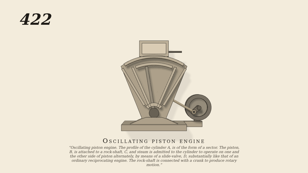
Oscillating piston engine. The profile of the cylinder A, is of the form of a sector. The piston, B, is attached to a rock-shaft, C, and steam is admitted to the cylinder to operate on one and the other side of piston alternately, by means of a slide-valve, D, substantially like that of an ordinary reciprocating engine. The rock-shaft is connected with a crank to produce rotary motion.
Only the input is driven; every other part of this model moves by physics (MuJoCo), and its ratios are measured. Run it live, change its parameters, or switch the friction off to see the output stop.
- Modelled as
- Brown's section through the sector-shaped cylinder A, no gravity. The piston B is a vane 11 cm long fast on the rock-shaft C at the sector's point, swinging between the sector's sides. Behind, an arm 5 cm long on the rock-shaft takes a rod of about 10 cm to a 1.6 cm crank on a shaft to the right, which carries a fly-wheel and works against a load. The steam (the one driven input) presses the piston one way and then the other, let in by the crank shaft's own position as the slide-valve D would let it in (greatest at mid-swing, nothing at the ends).
- Measured
- Started at rest, the crank shaft runs one way only (no run-back), over both dead-centres every turn, at about 5.5 rad/s (52 rev/min). The piston rocks through about 18.7 degrees either way of the middle, as the 1.6 cm crank on the 5 cm arm gives, and stays inside the sector; no part penetrates another.
- Notes
- The cylinder is cut through and only its back half is drawn, without hatching; the slide-valve D and its stem are drawn fixed in the valve-chest, the valve's timing being modelled by the crank's position; the arm, rod, crank, its pedestal and the fly-wheel (named in the text but not in the figure) are added behind the cylinder.
Film (MP4) · Still (PNG) · Spec (YAML) · Model (MJCF)