Buchanan & Righter’s patent slide-valve motion
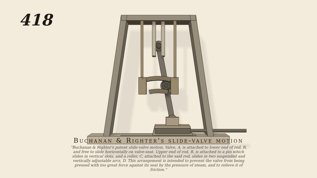
Buchanan & Righter’s patent slide-valve motion. Valve, A, is attached to lower end of rod, B, and free to slide horizontally on valve-seat. Upper end of rod, B, is attached to a pin which slides in vertical slots, and a roller, C, attached to the said rod, slides in two suspended and vertically adjustable arcs, D. This arrangement is intended to prevent the valve from being pressed with too great force against its seat by the pressure of steam, and to relieve it of friction.
Only the input is driven; every other part of this model moves by physics (MuJoCo), and its ratios are measured. Run it live, change its parameters, or switch the friction off to see the output stop.
- Modelled as
- Brown's front section, gravity on. The valve A is pinned to the lower end of the rod B and is driven to and fro along its seat by the valve-stem (the one driven joint, an oscillating slide). The upper end of B is pinned to a head that slides in the vertical slot at the top of the frame, and the roller C, on its own pin on the rod, runs on the two suspended arcs D. The valve is free to rise and fall on the stem; its weight stands for the steam pressure pressing it to the seat.
- Measured
- The arcs carry the roller and with it the valve: the valve sinks only about 0.1 mm of its 1 mm clearance and never comes to its seat, while the rod rocks in step with the stem (follow ratio within 4%, r^2 > 0.99) and the roller rolls along the arcs; no part penetrates another.
- Notes
- The steam load is the valve's own weight; the arcs are fixed at their set height (Brown's adjusting screw is not modelled); the steam chest is simplified to an open frame with the slot cheeks and seat.
Film (MP4) · Still (PNG) · Spec (YAML) · Model (MJCF)