Describing spiral line on a cylinder
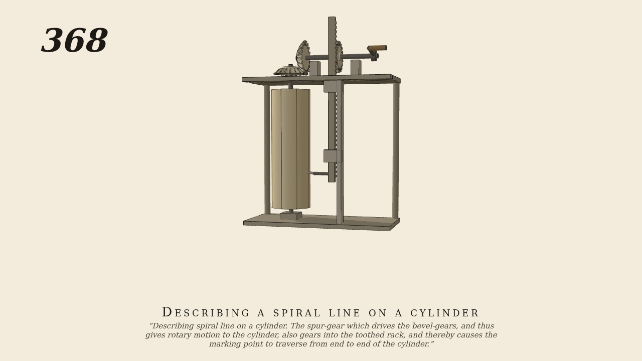
Describing spiral line on a cylinder. The spur-gear which drives the bevel-gears, and thus gives rotary motion to the cylinder, also gears into the toothed rack, and thereby causes the marking point to traverse from end to end of the cylinder.
Only the input is driven; every other part of this model moves by physics (MuJoCo), and its ratios are measured. Run it live, change its parameters, or switch the friction off to see the output stop.
- Modelled as
- The crank turns a horizontal cross-shaft above the table, the only driven part, at 8 rev/min. On it are a spur-gear of 20 teeth (module 0.35 cm, 7 cm across) and, at its left end, a bevel-gear of 20 teeth, which works an equal horizontal bevel-gear on the upright shaft of the cylinder (10 cm across, 30 cm long) hanging below the table, so the cylinder turns once for each turn of the crank. The spur-gear also gears into an upright toothed rack in front of it, sliding in guides beside the cylinder; the rack carries the marking point to the cylinder's face and lifts it from the bottom of the cylinder toward the top as the cylinder turns.
- Measured
- The cylinder turns at 1.0007 times the crank (the other way), and the rack rises 0.0350 m for each radian of the crank (theory: the spur's pitch radius, 0.035 m; r² 1.0000), so the point travels 22.0 cm along the cylinder for each turn of it and describes a spiral of that pitch, about 1.2 turns over the 26 cm traverse. Contact penetration stays under 0.01 mm after the first half second.
- Notes
- Brown gives no sizes. The layout follows his elevation (upright cylinder, cross-shaft above). The marking point is drawn just touching the cylinder's face and is not in contact, so no line is drawn on it. The frame posts are added only to carry the table.
Film (MP4) · Still (PNG) · Spec (YAML) · Model (MJCF)