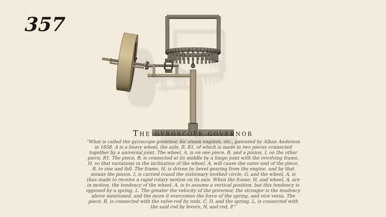
What is called the gyroscope governor, for steam engines, etc.,…
What is called the gyroscope governor, for steam engines, etc., patented by Alban Anderson in 1858. A is a heavy wheel, the axle, B, B1, of which is made in two pieces connected together by a universal joint. The wheel, A, is on one piece, B, and a pinion, I, on the other piece, B1. The piece, B, is connected at its middle by a hinge joint with the revolving frame, H, so that variations in the inclination of the wheel, A, will cause the outer end of the piece, B, to rise and fall. The frame, H, is driven by bevel gearing from the engine, and by that means the pinion, I, is carried round the stationary toothed circle, G, and the wheel, A, is thus made to receive a rapid rotary motion on its axis. When the frame, H, and wheel, A, are in motion, the tendency of the wheel, A, is to assume a vertical position, but this tendency is opposed by a spring, L. The greater the velocity of the governor, the stronger is the tendency above mentioned, and the more it overcomes the force of the spring, and vice versa. The piece, B, is connected with the valve-rod by rods, C, D, and the spring, L, is connected with the said rod by levers, N, and rod, P.
Only the input is driven; every other part of this model moves by physics (MuJoCo), and its ratios are measured. Run it live, change its parameters, or switch the friction off to see the output stop.
- Modelled as
- Frame H turns about the vertical and is the only driven part (set for 90 rev/min; it runs at 84 under load). The axle is in two pieces joined by a universal joint, a cross held by two pins. The inner piece B1 runs in a bearing on H and carries the lantern pinion I, 8 staves on a 3 cm circle, which rolls on top of the stationary circle G, 32 studs on a 12 cm circle, so B1 turns 4 times for each turn of H. The outer piece B is hinged at its middle to H and carries the heavy wheel A, 14 cm across, 3 cm thick, 3.65 kg, 5 cm outside the hinge. The spring L is a spring on B's hinge, 5 N·m per radian, wound to hold B level; a stop under B keeps the wheel from falling more than 0.02 rad.
- Measured
- The wheel spins at 4.0008 times the frame's rate (slip -0.02%), and the spin lifts the outer end of B against its weight and the spring. At 84 rev/min B stands 0.13 to 0.15 rad above level from 3 s on; the balance of spin torque, weight, spring and the wheel's outward pull gives 0.13. Run at 60 rev/min the wheel's weight wins and B rests on its stop; at 120 rev/min B rises to 0.38 rad. Contact penetration stays under 0.25 mm.
- Notes
- Brown gives no sizes. The valve rods C and D, the levers N and the rod P are left out: the spring L is put straight on B's hinge, and B's tilt is what the rods would carry to the valve. The bevel gearing from the engine is replaced by the drive on H.
Film (MP4) · Still (PNG) · Spec (YAML) · Model (MJCF)