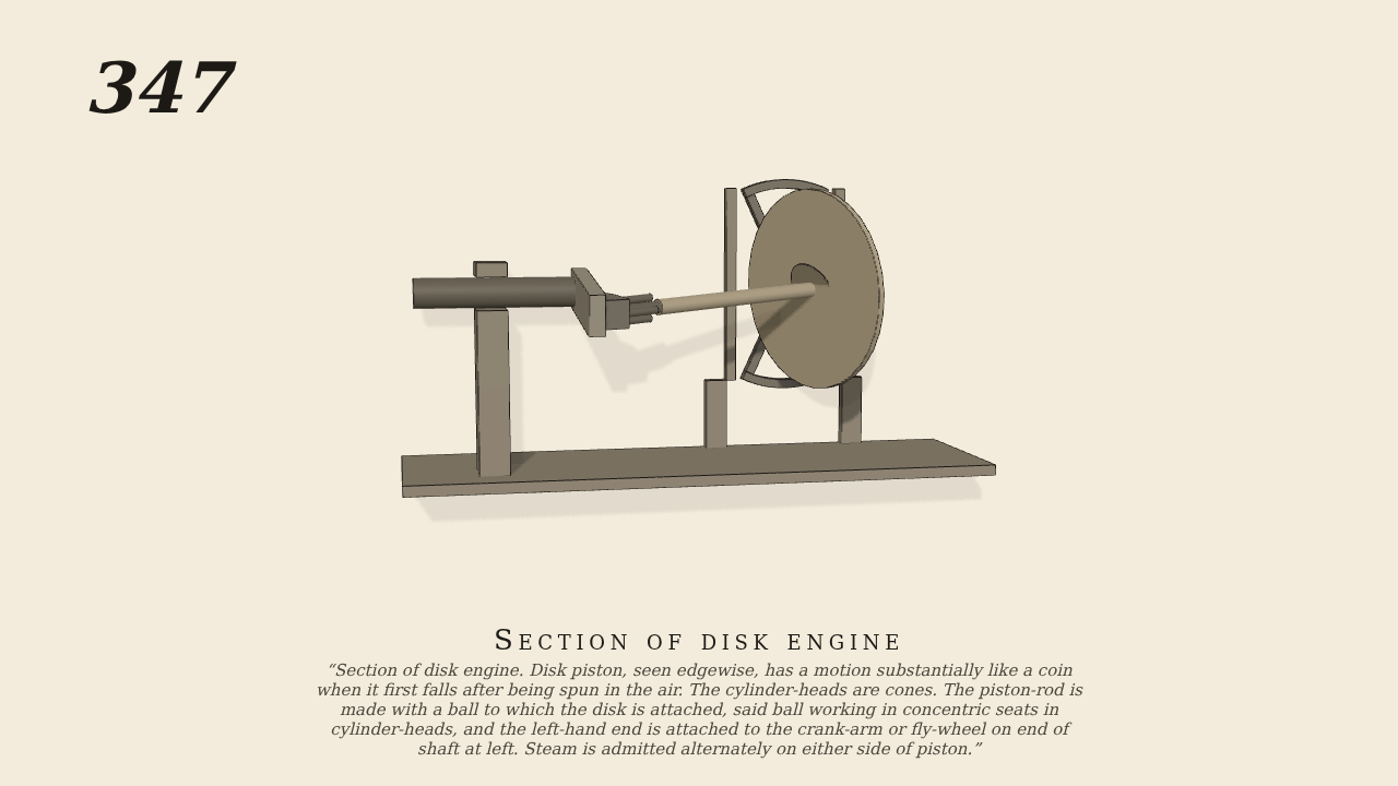
Section of disk engine
Section of disk engine. Disk piston, seen edgewise, has a motion substantially like a coin when it first falls after being spun in the air. The cylinder-heads are cones. The piston-rod is made with a ball to which the disk is attached, said ball working in concentric seats in cylinder-heads, and the left-hand end is attached to the crank-arm or fly-wheel on end of shaft at left. Steam is admitted alternately on either side of piston.
Only the input is driven; every other part of this model moves by physics (MuJoCo), and its ratios are measured. Run it live, change its parameters, or switch the friction off to see the output stop.
- Modelled as
- The disk piston, 27 cm across, is fixed on the ball of the piston-rod at the middle of the cylinder. The casing is drawn as a section plate behind the disk: the two conical cylinder-heads, the spherical zone between them, and the walls. The ball turns on a cross, a Hooke's joint, standing for the radial partition of a real disk engine. The partition keeps the disk from turning round the cylinder's axis. The disk can only rock. The shaft at the left carries a crank-arm. The arm's eye is four bars round the rod's end, 13 cm off the shaft's line and 28 cm from the ball, pointing at the ball, so the rod leans 24.9 degrees off the cylinder's axis. The rod's end is held in the eye only by contact, with 0.03 cm play. Hard stops on the cross stand for the disk coming to rest on the conical heads. The shaft is turned at 30 rev/min. It is the only driven part.
- Measured
- The crank-arm carries the rod's end round a circle, and the rod rocks the disk round like a settling coin. Each turn the disk rocks 24.9 degrees either side of upright, up and down and then side to side a quarter-turn later, without turning round the axis. The deepest contact is 0.02 mm.
- Notes
- Brown gives no sizes. They are taken roughly from the figure. The casing is drawn as a section plate behind the disk, as in the figure, so that the disk shows. The fly-wheel and the arc on the crank-arm are left out. The partition is modelled as a Hooke's joint at the ball. Here the shaft drives the disk, the reverse of a working engine, and no steam is simulated.
Film (MP4) · Still (PNG) · Spec (YAML) · Model (MJCF)