Table engine
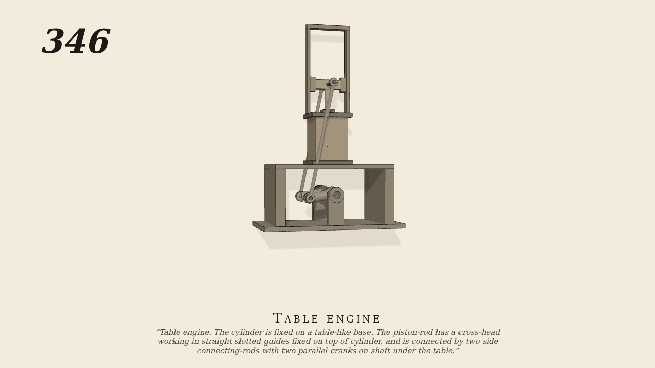
Table engine. The cylinder is fixed on a table-like base. The piston-rod has a cross-head working in straight slotted guides fixed on top of cylinder, and is connected by two side connecting-rods with two parallel cranks on shaft under the table.
Only the input is driven; every other part of this model moves by physics (MuJoCo), and its ratios are measured. Run it live, change its parameters, or switch the friction off to see the output stop.
- Modelled as
- The cylinder stands on a table-like base. Two straight slotted guides, joined by a bridge at the top, are fixed on the cylinder's top. The cross-head on the piston-rod has a shoe at each end, and each shoe runs between a guide bar and its own clearance of 0.02 cm. The cross-head's pin runs out on both sides of the cylinder. Two side connecting-rods, 39.2 cm long, one in front of the cylinder and one behind, have their upper eyes round the pin. Their lower ends are on two parallel cranks, 8 cm long, on the shaft under the table. Every eye on the cross-head pin is held there by contact, with a few hundredths of a centimetre play. The cross-head is free to move up, down and across and to turn, and only the guides and the rods place it. The shaft is turned at 30 rev/min. It is the only driven part.
- Measured
- The cross-head and piston-rod run the length of their 16 cm stroke, twice the cranks' length, once each turn. The two side rods swing together. The guides hold the cross-head to within 0.2 mm across, its play, and to 0.5 degree of turn. The deepest contact is 0.03 mm.
- Notes
- Brown gives no sizes. They are taken roughly from the figure. The camera is turned a little so that both side rods show. Here the crank drives the piston, the reverse of a working engine, and no steam is simulated.
Film (MP4) · Still (PNG) · Spec (YAML) · Model (MJCF)