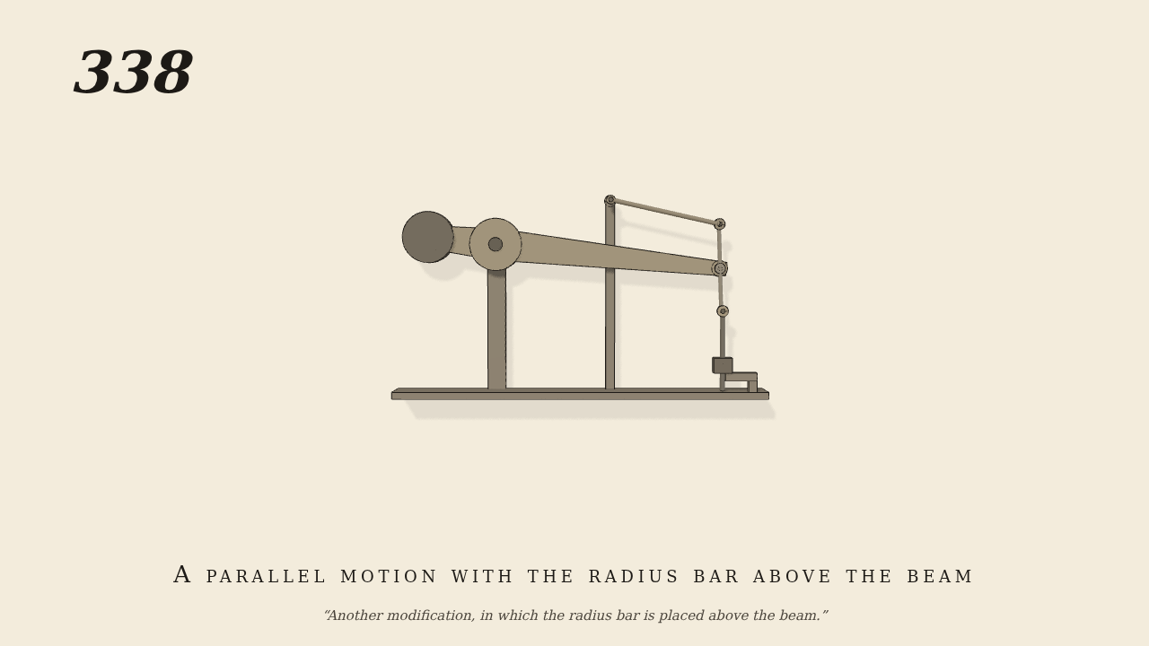
Another modification, in which the radius bar is placed above the beam
Another modification, in which the radius bar is placed above the beam.
Only the input is driven; every other part of this model moves by physics (MuJoCo), and its ratios are measured. Run it live, change its parameters, or switch the friction off to see the output stop.
- Modelled as
- Watt's linkage with both arms on the same side. The beam turns on O and is rocked through 0.14 radian each way. A rod passes through the beam's end U, 40 cm from O. Its upper end T, 7.8 cm above U, is held by the radius bar, which is 19.6 cm long and runs back from T over the beam to a fixed centre G. The piston-rod is pinned at the rod's lower end C, 7.5 cm below U. A weight on the beam's short end stands in for the engine's other side. Every joint is a pin in a ring with a few hundredths of a centimetre play. The cross-head is free to move up, down and across, and only the pin C places it. The beam is the only driven part.
- Measured
- The piston-rod rises and falls 11.1 cm, 0.399 m per radian of the beam, in step with it. The radius bar swings 2.06 times as far as the beam, the same way. C strays across by no more than 0.3 mm. The deepest contact is 0.01 mm.
- Notes
- Brown gives no sizes; lengths are taken from the figure. With both arms on the same side, the straight-moving point lies outside the rod T U, at UC = TU x GT / (OU - GT), here 7.5 cm. The figure puts it about 10.5 cm below U. On paper that would stray 1.8 mm, so the model uses 7.5 cm, which strays 0.15 mm. No steam is simulated.
Film (MP4) · Still (PNG) · Spec (YAML) · Model (MJCF)