Parallel motion for direct action engines
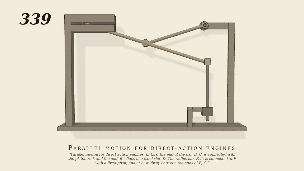
Parallel motion for direct action engines. In this, the end of the bar, B, C, is connected with the piston-rod, and the end, B, slides in a fixed slot, D. The radius bar, F, A, is connected at F with a fixed pivot, and at A, midway between the ends of B, C.
Only the input is driven; every other part of this model moves by physics (MuJoCo), and its ratios are measured. Run it live, change its parameters, or switch the friction off to see the output stop.
- Modelled as
- Scott Russell's parallel motion in its exact form. The radius bar F A is 20 cm long and turns on the fixed pivot F; it is rocked through 0.18 radian each way. Its pin A carries the middle of the bar B C, 40 cm long. The end B is a pin in the fixed slot D, which runs level with F. The piston-rod is pinned at the other end C, which hangs below F. Every joint is a pin in a ring, or in the slot, with a few hundredths of a centimetre play. The cross-head is free to move up, down and across, and only the pin C places it. The radius bar is the only driven part.
- Measured
- The piston-rod rises and falls 13 cm, 0.36 m per radian of the radius bar, in step with it. The bar B C turns twice as far as the radius bar, the other way, while B slides along the slot. C strays across by no more than 0.2 mm. The deepest contact is 0.01 mm.
- Notes
- Brown gives no sizes. F A, A B and A C are equal, as the figure shows, so C keeps to the upright line through F exactly; the slot sits level with F. The connecting-rod to the crank above, and the engine's framing, are left out. No steam is simulated. The drive is stiff enough to hold the bars' weight.
Film (MP4) · Still (PNG) · Spec (YAML) · Model (MJCF)