Conical pendulum, hung by a thin piece of round wire
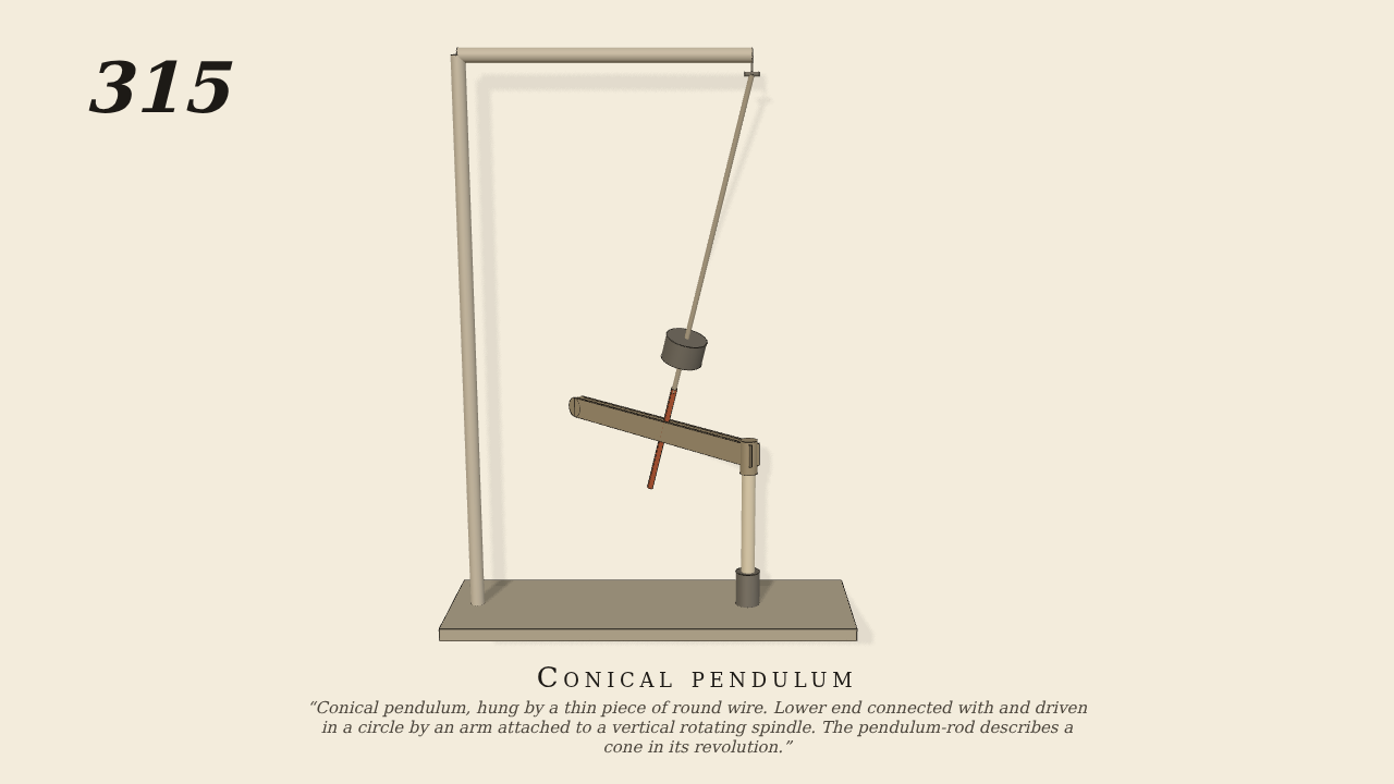
Conical pendulum, hung by a thin piece of round wire. Lower end connected with and driven in a circle by an arm attached to a vertical rotating spindle. The pendulum-rod describes a cone in its revolution.
Only the input is driven; every other part of this model moves by physics (MuJoCo), and its ratios are measured. Run it live, change its parameters, or switch the friction off to see the output stop.
- Modelled as
- Gravity is on. The pendulum hangs from a bracket at the top. A small gimbal of two crossed pivots stands in for the thin round wire: like the wire, it lets the rod swing any way but not twist. The rod is 40 cm long, the bob is 34 cm down, and the rod ends in a square pin 14 cm long. The pin stands in the slot of the arm on top of the vertical spindle below. The spindle is the one driven joint, at 56 turns a minute. The pin can slide out along the slot and up it, so the arm only carries the rod's end round. The pendulum flies out until gravity balances the spin, and the rod describes a cone. It is drawn 3° aside at the start.
- Measured
- The rod goes round with the spindle: the pendulum's swing about each pivot has a period of 1.0718 s, and the spindle takes 1.0714 s a turn. The swings about the two pivots are equal (34.9°), so the path is a cone, not a swing in a plane. The cone's half-angle agrees with the conical pendulum's rule, cos θ = (turn period / pendulum's own period)². With the compound pendulum's 1.1806 s, that gives 34.5°. The deepest contact is 0.06 mm.
- Notes
- Brown gives no sizes. The length, the bob and the speed are choices. The speed has to be above the pendulum's own swing rate, or it will not fly out. The wire is drawn above the gimbal, which does its work: two pivots that swing freely. The spindle is held at its speed by a velocity drive, the engine or train that turns it. The arm drives only the rod's end: the cone's angle is the pendulum's own.
Film (MP4) · Still (PNG) · Spec (YAML) · Model (MJCF)