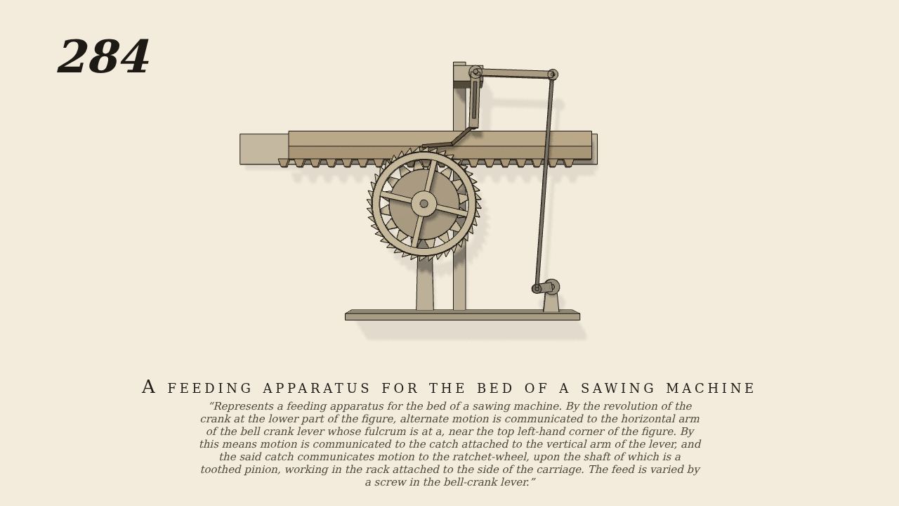
A feeding apparatus for the bed of a sawing machine
Represents a feeding apparatus for the bed of a sawing machine. By the revolution of the crank at the lower part of the figure, alternate motion is communicated to the horizontal arm of the bell crank lever whose fulcrum is at a, near the top left-hand corner of the figure. By this means motion is communicated to the catch attached to the vertical arm of the lever, and the said catch communicates motion to the ratchet-wheel, upon the shaft of which is a toothed pinion, working in the rack attached to the side of the carriage. The feed is varied by a screw in the bell-crank lever.
Only the input is driven; every other part of this model moves by physics (MuJoCo), and its ratios are measured. Run it live, change its parameters, or switch the friction off to see the output stop.
- Modelled as
- A crank at the lower right is the one driven joint, at 30 turns a minute with a 2.43 cm throw. A connecting-rod, pinned at both ends, works the 12 cm horizontal arm of a bell-crank lever whose fulcrum a is at the top. The lever's 8 cm vertical arm carries the catch on a pin. The catch is sprung and lies on top of a 40-tooth ratchet-wheel (radius 9 cm). As the rod pulls the arm down, the catch pushes the wheel round by real contact; as the rod rises, it slides back over the teeth. Its 3.24 cm of travel is 2.4 tooth pitches, so the wheel turns two teeth for each turn of the crank. Between strokes the wheel is held by its bearing friction. A 16-tooth pinion on the wheel's shaft (module 0.8, pitch radius 6.4 cm) works the rack on the side of the carriage above it. Gravity is on.
- Measured
- The wheel turns 0.0499 of a turn for each turn of the crank (expected 2/40 = 0.05; slip 0.24%). Its largest run-back is 0.10 degrees. The catch rides over the teeth on every up-stroke (7 clicks in 10 s). The carriage follows the wheel at −6.42 cm per radian (r² 0.9992), so it feeds to the left by about 2 cm for each turn of the crank. The deepest contact after 0.5 s is 0.17 mm.
- Notes
- Brown gives no sizes. The screw in the bell-crank lever that varies the feed (by moving the catch's pin along the vertical arm) is drawn but not modelled. The catch here pushes on the top of the wheel; in the plate it hooks the wheel's side.
Film (MP4) · Still (PNG) · Spec (YAML) · Model (MJCF)