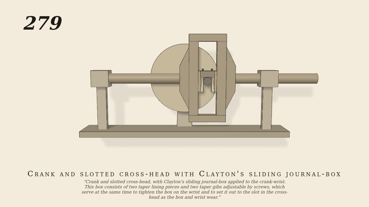
Crank and slotted cross-head, with Clayton’s sliding journal-box…
Crank and slotted cross-head, with Clayton’s sliding journal-box applied to the crank-wrist. This box consists of two taper lining pieces and two taper gibs adjustable by screws, which serve at the same time to tighten the box on the wrist and to set it out to the slot in the cross-head as the box and wrist wear.
Only the input is driven; every other part of this model moves by physics (MuJoCo), and its ratios are measured. Run it live, change its parameters, or switch the friction off to see the output stop.
- Modelled as
- A crank on a shaft along y is the one driven joint, at 30 turns a minute. Its wrist is 4 cm from the shaft. Clayton's box (3.2 by 3.6 cm) turns on the wrist. It is built from two taper lining pieces round the wrist, two taper gibs behind them, a cap, and the two screws that set the gibs down. The box's two sides work by real contact in the upright slot of the cross-head, with 0.1 mm of play on each side. The cross-head slides along x in guides on two rods.
- Measured
- The cross-head follows x = 4 sin θ cm. Its slope is 0.0400 m/rad at mid-stroke (r² 1.0000) and ±0.0283 m/rad at 45° and 135° (r² 0.9997), the same on both sides as for a harmonic motion with no obliquity. The stroke is −4.01 to 4.01 cm. The slot keeps the box upright: it turns back on the wrist at −1.0000 rad per radian of crank. The deepest contact is 0.01 mm.
- Notes
- Brown gives no sizes. The linings, gibs and screws are modelled as one rigid box, set to the slot with 0.1 mm of play. The wear adjustment is shown in the drawing but is not exercised in the simulation.
Film (MP4) · Still (PNG) · Spec (YAML) · Model (MJCF)