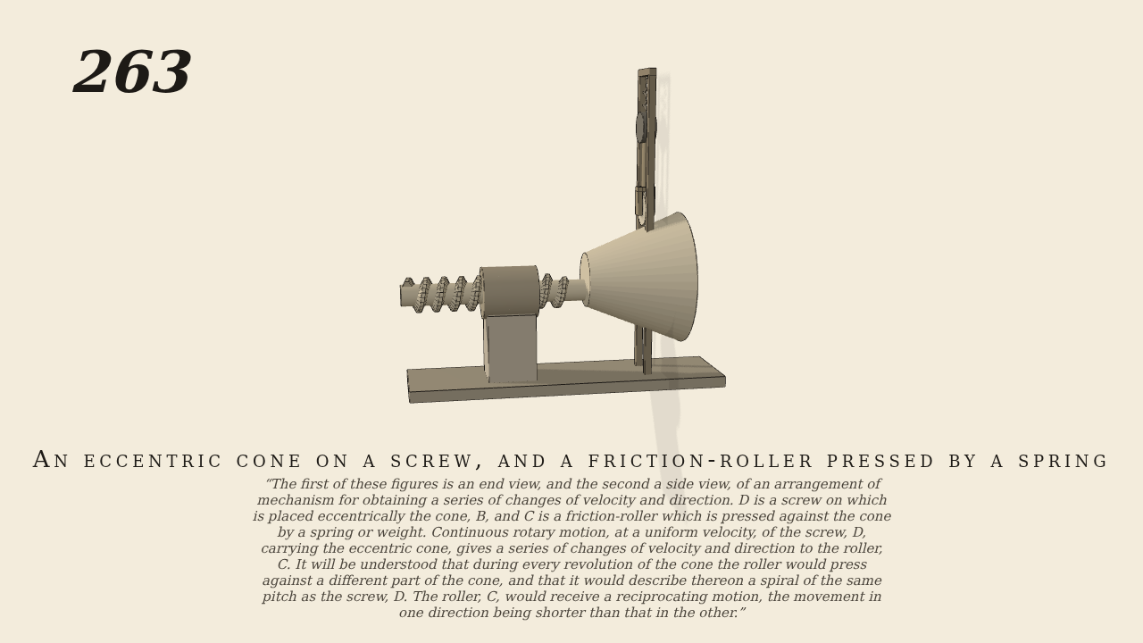
The first of these figures is an end view, and the second a side…
262-263. The first of these figures is an end view, and the second a side view, of an arrangement of mechanism for obtaining a series of changes of velocity and direction. D is a screw on which is placed eccentrically the cone, B, and C is a friction-roller which is pressed against the cone by a spring or weight. Continuous rotary motion, at a uniform velocity, of the screw, D, carrying the eccentric cone, gives a series of changes of velocity and direction to the roller, C. It will be understood that during every revolution of the cone the roller would press against a different part of the cone, and that it would describe thereon a spiral of the same pitch as the screw, D. The roller, C, would receive a reciprocating motion, the movement in one direction being shorter than that in the other.
Only the input is driven; every other part of this model moves by physics (MuJoCo), and its ratios are measured. Run it live, change its parameters, or switch the friction off to see the output stop.
- Modelled as
- Side view of Brown's pair, gravity on, shafts level: the machine of No. 262, the friction-roller pressed by a spring. The screw D (pitch 1.6 cm, 20 turns a minute, the one driven joint) works in a fixed two-turn nut and travels 1.6 cm a turn, free in its carriage. The cone B, fast on D, runs from radius 2.5 to 6.1 cm over 9 cm, its axis 1.2 cm off D's. The roller C (radius 1.5 cm), over D's axis in a vertical slide of 0.3 kg, is pressed on the cone by a spring of 400 N/m, set to 9.8 N at the start. The eccentricity lifts and drops C 2.4 cm a turn while the travelling cone brings wider circles under it, so C traces a spiral of the screw's pitch and rises further than it falls. Only the threads and the cone's contact on C touch.
- Measured
- The screw travels -0.0025 m per radian of D (ideal -0.0025, r2 1.000). C follows the cone at 0.0132 m/rad at its fastest rise and -0.0111 at its fastest fall (ideal 0.0132 and -0.0111, r2 0.999), and ranges -0.94 to 2.44 cm about its start (ideal -0.92 to 2.45): strokes +2.73 and -2.09 cm. C spins by friction at 2.21 to 4.41 of D in slices (ideal 2.24 to 4.49 at the extremes). The deepest contact is 0.03 mm.
- Notes
- Brown gives no sizes; the shared text describes both figures, built as one machine: No. 262 the end view with a weight, this the side view with a spring. The spring is the slide joint's own stiffness, its free length 2.45 cm below C's start; the slide carries a damper of 2 N s/m so C does not ring on it.
Film (MP4) · Still (PNG) · Spec (YAML) · Model (MJCF)