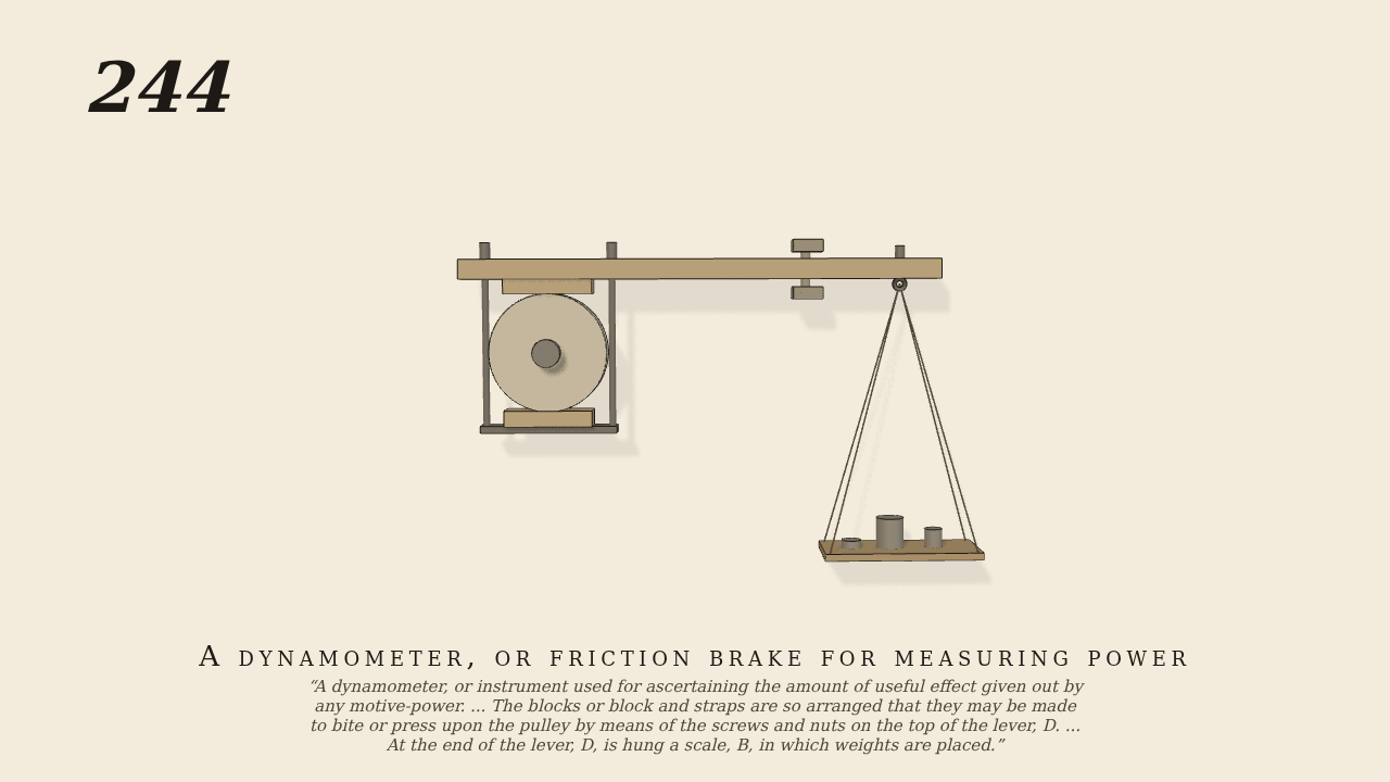
A dynamometer, or instrument used for ascertaining the amount of…
A dynamometer, or instrument used for ascertaining the amount of useful effect given out by any motive-power. It is used as follows:—A is a smoothly-turned pulley, secured on a shaft as near as possible to the motive-power. Two blocks of wood are fitted to this pulley, or one block of wood and a series of straps fastened to a band or chain, as in the drawing, instead of a common block. The blocks or block and straps are so arranged that they may be made to bite or press upon the pulley by means of the screws and nuts on the top of the lever, D. To estimate the amount of power transmitted through the shaft, it is only necessary to ascertain the amount of friction of the drum, A, when it is in motion, and the number of revolutions made. At the end of the lever, D, is hung a scale, B, in which weights are placed. The two stops, C, C', are to maintain the lever as nearly as possible in a horizontal position. Now, suppose the shaft to be in motion, the screws are to be tightened and weights added in B, until the lever takes the position shown in the drawing at the required number of revolutions. Therefore the useful effect would be equal to the product of the weights multiplied by the velocity at which the point of suspension of the weights would revolve if the lever were attached to the shaft.
Only the input is driven; every other part of this model moves by physics (MuJoCo), and its ratios are measured. Run it live, change its parameters, or switch the friction off to see the output stop.
- Modelled as
- The pulley A (radius 6) is on the engine's shaft, turned at 120 rev/min by a velocity servo, the one driven joint, whose torque is what the brake measures. The lever D (wood) turns freely about the shaft's axis. Its own block of wood lies on the pulley's top, and the lower block hangs from it on the two screws. The screws are a slide in the lever with a spring for their grip (the nuts' setting, turned by the operator's hand). Blocks on pulley are real contact (friction 0.3, wood on iron). The scale B (1.5 kg with its weights) hangs on its eye 36 from the shaft's axis. The stops C and C' are frame blocks 0.8 below and above the lever (about ±0.03 rad). A damper on the lever stands for the operator's steadying hand, the brake's dashpot; it carries no torque when the lever is still. The hand's schedule follows Brown: screws slack, screwed up at 1.5 s until the lever rises off C, eased back at 2.4 s until it hangs level.
- Measured
- With the screws slack the lever rests on C (-0.029 rad) and the shaft runs almost free (0.03 N·m). Screwed up, the blocks' friction (6.6 N·m) lifts the lever off C. Eased back, the lever hangs level between the stops, within 0.003–0.005 rad for 3.2 s. Meanwhile the shaft's mean torque is 5.74 N·m, against 5.70 N·m for the moment of the scale and of the lever's own weight about the shaft, taken from the model (1.874 kg at 31.0). A sweep of the screws' setting shows the lever first lifting off C at 5.70 N·m: the balance Brown's rule relies on, the useful effect being the weight's moment times the shaft's speed. The shaft turns at 11.6 rad/s under the brake, and the deepest contact is 0.54 mm.
- Notes
- Brown gives no sizes. The screws' setting is the operator's adjustment: about 1.55 is the balance (the lever just lifting), and the friction's scatter of about ±0.1 N·m makes the lever creep slowly one way or the other. That is why the stops are there, and why the run screws up past the balance to lift the lever and then eases back, as Brown's operator does. The lever's own weight is included in the moment; a real brake is counterpoised or weighed empty first.
Film (MP4) · Still (PNG) · Spec (YAML) · Model (MJCF)