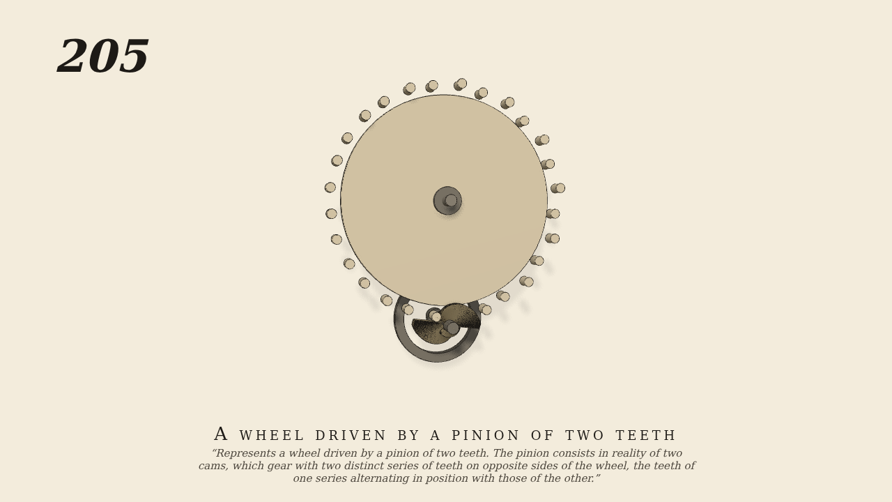
A wheel driven by a pinion of two teeth
Represents a wheel driven by a pinion of two teeth. The pinion consists in reality of two cams, which gear with two distinct series of teeth on opposite sides of the wheel, the teeth of one series alternating in position with those of the other.
Only the input is driven; every other part of this model moves by physics (MuJoCo), and its ratios are measured. Run it live, change its parameters, or switch the friction off to see the output stop.
- Modelled as
- The wheel carries two rows of 14 pins, one standing out of each face on a circle of radius 10, the back row midway between the front. Below it the pinion's shaft, the only driven joint (30 rpm), carries two one-lobed cams half a turn apart, each in the plane of one row. Each cam's outline is the largest the pins leave free when wheel and pinion turn together at 1/14 (pinion pitch radius 0.714), less 0.05 clearance, kept to a 200-degree lobe and cut to the hub elsewhere. The front cam drives the front row for part of a turn, then the back cam the back row. A fly-wheel behind steadies the slender shaft.
- Measured
- Over 1-7 s the wheel turns -0.0714 times the pinion (-1/14), with 0.01% slip. Contacts alternate between the front and back planes. Max penetration 0.00 mm after 1 s.
- Notes
- The wheel carries a 0.05 N m friction load so that it moves only when a cam pushes it. The plate's teeth are drawn as round pins, and the bearings are drawn only.
Film (MP4) · Still (PNG) · Spec (YAML) · Model (MJCF)