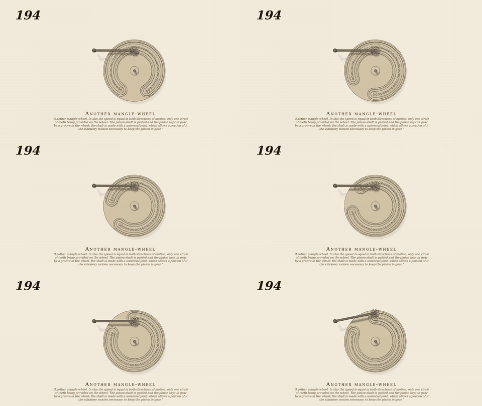
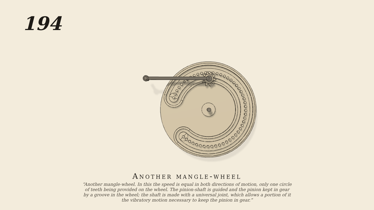
Another mangle-wheel
Another mangle-wheel. In this the speed is equal in both directions of motion, only one circle of teeth being provided on the wheel. With all of these mangle-wheels the pinion-shaft is guided and the pinion kept in gear by a groove in the wheel. The said shaft is made with a universal joint, which allows a portion of it to have the vibratory motion necessary to keep the pinion in gear.
Only the input is driven; every other part of this model moves by physics (MuJoCo), and its ratios are measured. Run it live, change its parameters, or switch the friction off to see the output stop.
- Modelled as
- One circle of 50 pins (radius 12) over 294 degrees and a guiding groove a track 2 inside and 2 outside the pins, joined round the two end pins. The 10-tooth pinion (pitch radius 2, driven 30 rpm one way) turns at the end of a 20 cm arm pivoted on the frame, the swinging portion of the universal-jointed pinion shaft; its follower in the groove swings it 0.2 rad to keep the pinion in gear inside and outside the pins. A weight behind the face plate balances the gap. gen194.py.
- Measured
- Inside: ratio 0.1670 (kinematic rp/R = 0.1667); outside: -0.1665 (kinematic -0.1667), the same speed back; the arm swings 0.20 rad; penetration 0.10 mm.
- Notes
- The universal joint is shown as its swinging portion, an arm on a pivot (plan view of the shafts vibration).
Film (MP4) · GIF · Still (PNG) · Spec (YAML) · Model (MJCF)