Water-wheel governor acting on the same principle as 161, but by…
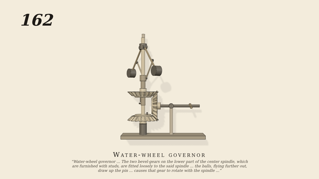
Water-wheel governor acting on the same principle as 161, but by different means. The governor is driven by the top horizontal shaft and bevel-gears, and the lower gears control the rise and fall of the shuttle or gate over or through which the water flows to the wheel. The action is as follows:—The two bevel-gears on the lower part of the center spindle, which are furnished with studs, are fitted loosely to the said spindle and remain at rest so long as the governor has a proper velocity; but immediately that the velocity increases, the balls, flying further out, draw up the pin which is attached to a loose sleeve which slides up and down the spindle, and this pin, coming in contact with the stud on the upper bevel gear, causes that gear to rotate with the spindle and to give motion to the lower horizontal shaft in such a direction as to make it raise the shuttle or gate, and so reduce the quantity of water passing to the wheel. On the contrary, if the speed ot the governor decreases below that required, the pin falls and gives motion to the lower bevel-gear, which drives the horizontal shaft in the opposite direction and produces a contrary effect.
Only the input is driven; every other part of this model moves by physics (MuJoCo), and its ratios are measured. Run it live, change its parameters, or switch the friction off to see the output stop.
- Modelled as
- No. 161's ball governor (gravity on) with a long sleeve that carries a pin down between two loose bevel-gears (miters, apex on the spindle), each with a stud on its inner face; both gear a third bevel on the lower horizontal shaft, which goes to the gate (the gate and wheel are not drawn; a friction load of 0.03 N m stands for them). The spindle is the one driven joint: a servo for 120 rpm with only 0.08 N m, so it runs up from rest over a few seconds and passes through the governor's speeds. Below speed the balls hang in, the pin is down behind the lower bevel's stud and carries it round; at the proper speed the pin stands between the studs and both bevels rest; above it the pin is up against the upper bevel's stud. Only pin on stud and tooth on tooth drive; the sleeve has a stop at the top.
- Measured
- Running up: 0.3-1.2 s lower bevel/spindle 0.999 and lower shaft/spindle +0.999; 2.2-3.0 s the sleeve stands 1.5-3.5 cm up, between the studs, and the lower shaft stands (11.21-11.22 rad); 5-9.8 s the sleeve is up 3.3-4.2 cm, upper bevel/spindle 1.000 and lower shaft/spindle -1.000 (the other way). Max penetration 0.19 mm.
- Notes
- The bevels are light (density 2700) so the pin takes them up without bouncing. Between the band and full engagement (about 3-4 s) the pin catches the upper stud a few times as the speed dips under the new load, as a real governor hunts.
Film (MP4) · Still (PNG) · Spec (YAML) · Model (MJCF)