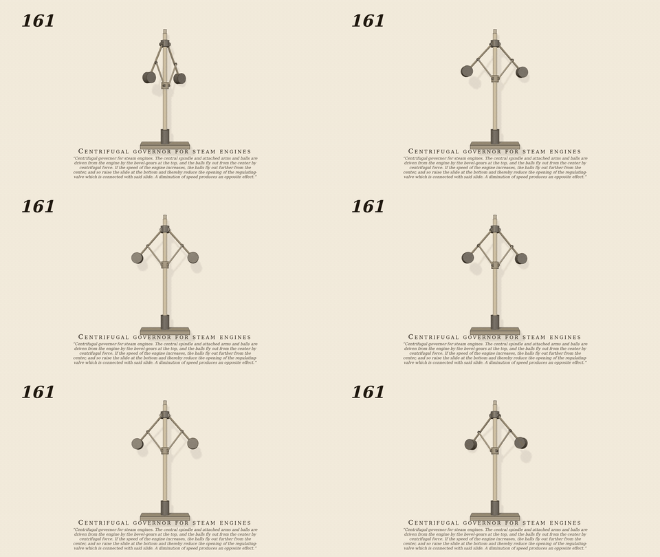
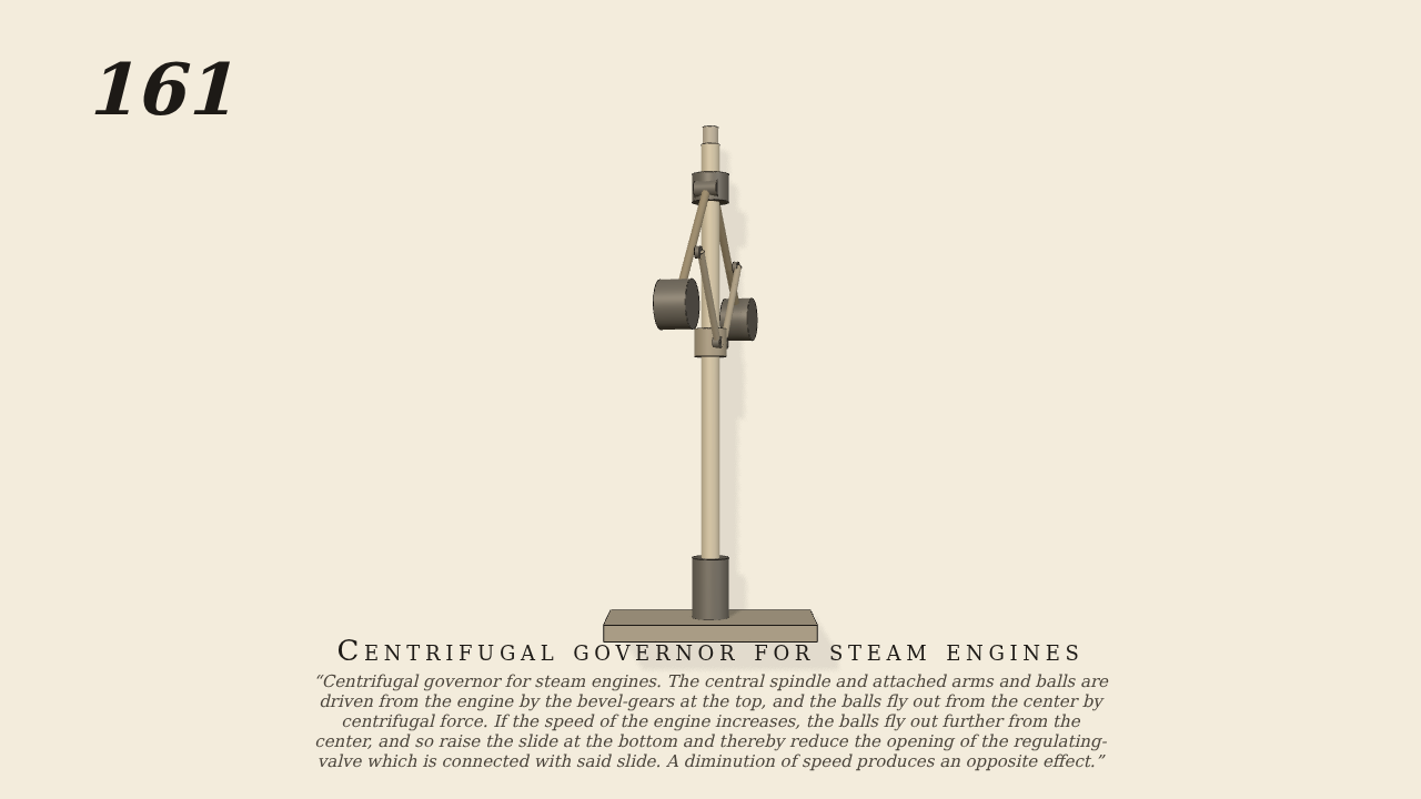
Centrifugal governor for steam engines
Centrifugal governor for steam engines. The central spindle and attached arms and balls are driven from the engine by the bevel-gears at the top, and the balls fly out from the center by centrifugal force. If the speed of the engine increases, the balls fly out further from the center, and so raise the slide at the bottom and thereby reduce the opening of the regulating-valve which is connected with said slide. A diminution of speed produces an opposite effect.
Only the input is driven; every other part of this model moves by physics (MuJoCo), and its ratios are measured. Run it live, change its parameters, or switch the friction off to see the output stop.
- Modelled as
- The spindle (turned at 100 rpm: the one driven joint; the engine and the bevel-gears at its top are not drawn) carries two 14 cm arms hinged at its top, each with a 0.4 kg ball. A link of 9 cm, pinned at both ends, joins each arm to a sleeve (the slide) that rides on the spindle with a weight of 0.2 kg. Gravity is on. The spin makes the balls fly out; their links draw the sleeve up. gen161.py. The bevel-gears are not modelled.
- Measured
- The balls fly out from 25 degrees to about 41 (the energy balance of spin, balls and sleeve gives 43) and the sleeve rises 2.3 cm. The sleeve follows the arm at 0.1004 m/rad as the geometry says (0.1001, r2 0.9992). The two arms agree (ratio 1.000). Penetration 0.
- Notes
- The arms are not point masses (the rod weighs a little), which accounts for the 2 degrees under the ideal. Hinge damping 0.004 settles the swing in about 3 s.
Film (MP4) · GIF · Still (PNG) · Spec (YAML) · Model (MJCF)