Circular motion into alternate rectilinear motion
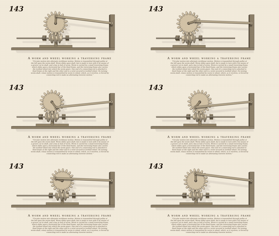
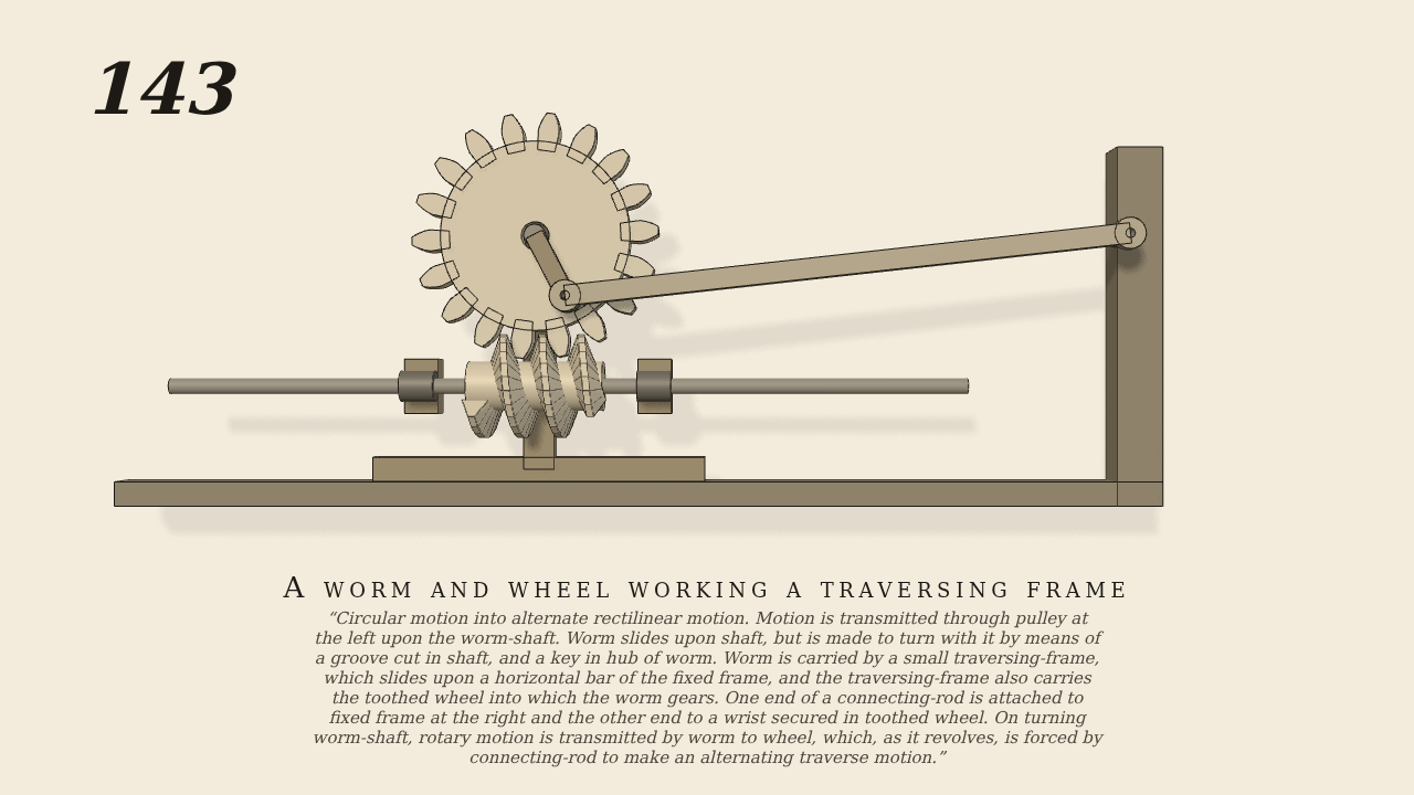
Circular motion into alternate rectilinear motion. Motion is transmitted through pulley at the left upon the worm-shaft. Worm slides upon shaft, but is made to turn with it by means of a groove cut in shaft, and a key in hub of worm. Worm is carried by a small traversing-frame, which slides upon a horizontal bar of the fixed frame, and the traversing-frame also carries the toothed wheel into which the worm gears. One end of a connecting-rod is attached to fixed frame at the right and the other end to a wrist secured in toothed wheel. On turning worm-shaft, rotary motion is transmitted by worm to wheel, which, as it revolves, is forced by connecting-rod to make an alternating traverse motion.
Only the input is driven; every other part of this model moves by physics (MuJoCo), and its ratios are measured. Run it live, change its parameters, or switch the friction off to see the output stop.
- Modelled as
- An 18-tooth wheel (module 0.8) lies face-on on a traversing frame, with a right-hand single-thread worm of 3 turns (72 convex segments) along x under it. Both are carried by the frame, which slides to and fro on a fixed bar. A worm sliding on a keyed shaft turns with it, so the one driven joint is the worm turning relative to the frame it rides in (180 turns a minute). The wheel is turned by the thread alone, 1/18 of a turn per worm turn. A wrist 4.5 cm from the centre of the wheel is joined by a 36.3 cm connecting rod to a pin on the fixed post at the right, so the wheel turning forces the frame to traverse: gen143.py.
- Measured
- Wheel / worm 0.0555 (expect 1/18 = 0.0556, slip 0.11%). The frame follows the crank-and-rod solution in five windows of 1 s at the fast parts of the traverse: slopes +0.0441 / -0.0441 / +0.0441 / -0.0440 / -0.0404 m per rad of the wheel (expect +0.0438 / -0.0437 / +0.0438 / -0.0437 / -0.0418, r2 0.996 or better); travel -4.78..+4.22 cm. Penetration 0.02 mm.
- Notes
- Without gravity (a plan). The plate shows the worm on its keyed shaft; in the model the shaft is drawn and the worm (turning with it) is driven relative to the frame, since the worm and wheel both ride on the frame. The windows are timed from the start-up lag of the servo (0.1 s).
Film (MP4) · GIF · Still (PNG) · Spec (YAML) · Model (MJCF)