A uniform intermittent rotary motion in opposite directions is…
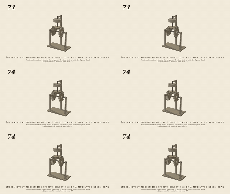
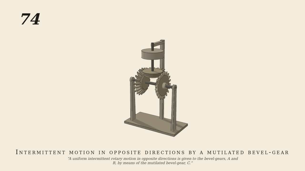
A uniform intermittent rotary motion in opposite directions is given to the bevel-gears, A and B, by means of the mutilated bevel-gear, C.
Only the input is driven; every other part of this model moves by physics (MuJoCo), and its ratios are measured. Run it live, change its parameters, or switch the friction off to see the output stop.
- Modelled as
- A and B, 20-tooth miter bevels (pitch radius 6), turn loose on a fixed horizontal arbor facing each other; C on the upright shaft (the only driven joint, with a pulley as flywheel) is the same bevel with 9 of its 20 teeth left. Every tooth is its own convex loft built from the src/geom/bevel.ts geometry (the No. 53 bevels), so C can lose teeth; only teeth collide. The toothed arc (162 deg) meets A on one side and B on the other, never both; A and B are held in dwell by bearing friction (frictionloss 0.05).
- Measured
- A/C -0.5015 vs -1/2 and B/C +0.5014 vs +1/2 (0.3% driver lag under the bearing friction; three whole turns, mid-dwell to mid-dwell: A steps exactly pi = 10 pitches a turn, 3.0006 pi over three); A and B still in dwell (0.0000 rad/s); max penetration 0.07 mm.
- Notes
- n teeth push n + 1: the approach of the first tooth and the recess of the last add a pitch, and the dwell must repeat in phase with the teeth of C, so the step is a whole number of pitches (KEEP 6 gave 7.02, KEEP 9 gives 10.00 pitches a turn). Tested under the Nix flake env.
Film (MP4) · GIF · Still (PNG) · Spec (YAML) · Model (MJCF)