To the driving-wheel, D, is secured a bent spring, B; another…
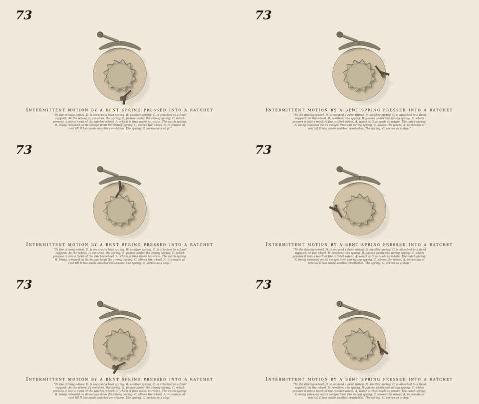
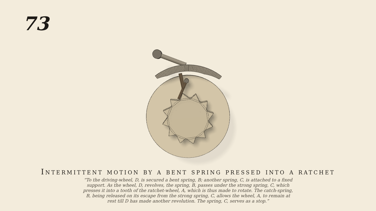
To the driving-wheel, D, is secured a bent spring, B; another spring, C, is attached to a fixed support. As the wheel, D, revolves, the spring, B, passes under the strong spring, C, which presses it into a tooth of the ratchet-wheel, A, which is thus made to rotate. The catch-spring, B, being released on its escape from the strong spring, C, allows the wheel, A, to remain at rest till D has made another revolution. The spring, C, serves as a stop.
Only the input is driven; every other part of this model moves by physics (MuJoCo), and its ratios are measured. Run it live, change its parameters, or switch the friction off to see the output stop.
- Modelled as
- D (only driven joint) carries the bent spring B, a sprung catch on a pin (joint stiffness/springref holds it out on its range stop). Ratchet A (12 teeth) is free on the same axis with light arbor friction (frictionloss 0.003). The strong spring C is a lever on a fixed centre preloaded onto its stop (stiffness 0.5, springref -0.2); its shoe (lead-in ramp, 1.5-tooth flat, run-out) presses B in by real contact. Tooth faces lean forward 55 deg so a driving face pushes B out: B can only drive while C holds it in, and springs out when its heel leaves the shoe. Self-indexing: one tooth per D turn.
- Measured
- Ratio j_a/j_d 0.0835 vs 1/12 (-0.22%, driver lag during engagement; per-turn advance at mid-dwell 0.5236 = 2pi/12). A still in dwell (0.0000 rad/s); B pressed 5 times in 23 s; max penetration 0.30 mm.
- Notes
- C acting as a stop for A is represented by A arbor friction plus the self-indexing shoe rather than a separate stop. Radial (locking) faces make B self-lock and carry A round continuously.
Film (MP4) · GIF · Still (PNG) · Spec (YAML) · Model (MJCF)