The small pulley at the top being the driver, the large,…
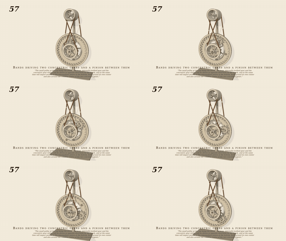
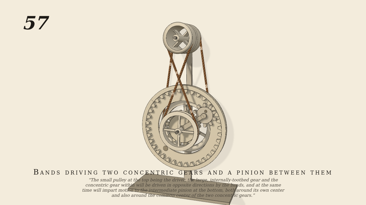
The small pulley at the top being the driver, the large, internally-toothed gear and the concentric gear within will be driven in opposite directions by the bands, and at the same time will impart motion to the intermediate pinion at the bottom, both around its own center and also around the common center of the two concentric gears.
Only the input is driven; every other part of this model moves by physics (MuJoCo), and its ratios are measured. Run it live, change its parameters, or switch the friction off to see the output stop.
- Modelled as
- Brown's figure 57: the small top pulley (r 5, the driven shaft) drives the internal gear (36) by an open cord band to a pulley (r 10) on its back, and the concentric gear (16) by a crossed band to a pulley (r 7) in front; the pinion (10) gears with both on a pin in an arm free about the common centre
- Measured
- internal gear 0.4911 (5.4/10.4 ≈ 0.52 less creep), inner gear −0.6935 (−0.73 less creep), arm 0.1271 (from the measured gear speeds, (36·0.4911 − 16·0.6935)/52 = 0.1266); gear penetration 0.06 mm; also passes at 45 rpm
- Notes
- Two elastic cord bands of links, friction only; teeth as No. 55. The pulley rims collide as capsules, so the two band planes are set 9.2 apart (a cord wrapping the smaller pulley would otherwise lie inside the larger rim's end cap). PGS. 8 s sim, ~3.5 min wall. batch7/gen057.py. Negative control: the pinion's teeth out of contact → the arm only drags (−0.031).
Film (MP4) · GIF · Still (PNG) · Spec (YAML) · Model (MJCF)