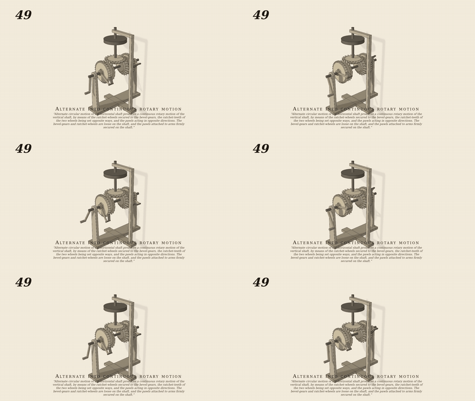
Alternate circular motion of the horizontal shaft produces a…
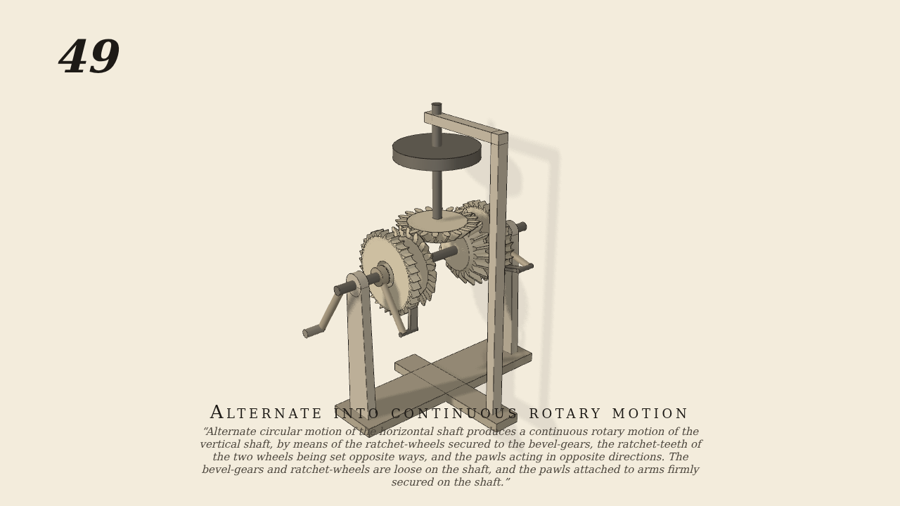
Alternate circular motion of the horizontal shaft produces a continuous rotary motion of the vertical shaft, by means of the ratchet-wheels secured to the bevel-gears, the ratchet-teeth of the two wheels being set opposite ways, and the pawls acting in opposite directions. The bevel-gears and ratchet-wheels are loose on the shaft, and the pawls attached to arms firmly secured on the shaft.
Only the input is driven; every other part of this model moves by physics (MuJoCo), and its ratios are measured. Run it live, change its parameters, or switch the friction off to see the output stop.
- Modelled as
- the horizontal shaft (rocked ±0.6 rad at 0.5 Hz by the hand: a velocity servo of its swing) carries two 20-tooth miter bevels loose on it, each cast with a 32-tooth ratchet wheel outboard, teeth set opposite ways; a sprung pawl on an arm keyed to the shaft outside each wheel; the upright shaft's bevel meshes both and carries a flywheel and a load
- Measured
- upright advances −0.982 rad per swing of the shaft (2×0.6 rad, less up to one ratchet tooth of lost motion at each reversal: expect −1.004 ± 6%), one way only (largest run-back 0.026 rad), pawls click over the teeth 18 and 25 times; penetration 0.20 mm; one-way at 0.6–1.5× amplitude and 0.6–1.6× frequency (0.79–0.90 of the shaft's travel)
- Notes
- Each bevel is driven only by its pawl on its ratchet teeth, the upright only by the bevel teeth. New: bevels keyed to parts (openspec add-bevel-on-part). batch7/gen049.py. Negative control: pawls out of contact → the upright stands (0.0000).
Film (MP4) · GIF · Still (PNG) · Spec (YAML) · Model (MJCF)