Ordinary steering apparatus
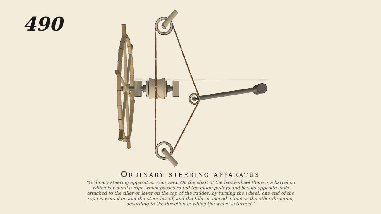
Ordinary steering apparatus. Plan view. On the shaft of the hand-wheel there is a barrel on which is wound a rope which passes round the guide-pulleys and has its opposite ends attached to the “tiller” or lever on the top of the rudder; by turning the wheel, one end of the rope is wound on and the other let off, and the tiller is moved in one or the other direction, according to the direction in which the wheel is turned.
Only the input is driven; every other part of this model moves by physics (MuJoCo), and its ratios are measured. Run it live, change its parameters, or switch the friction off to see the output stop.
- Modelled as
- Seen from above, as Brown's plan, gravity on. The hand-wheel (68 cm across, upright, seen edge-on) is keyed to a barrel 6 cm in radius whose shaft lies fore and aft in two bearings. The tiller-rope takes a full turn round the barrel, runs off its top to two guide pulleys on upright pins, one each side, and from them to the boss at the end of the tiller (44 cm long, on the rudder head), round which it is seized. The hand turning the wheel to and fro (2.6 rad each way) is the only input; the rudder's resistance in the water is a 3 N m s drag on the rudder head. The rope is a real cord, a chain of links, pretensioned, and grips the barrel and the boss by friction.
- Measured
- Turning the wheel winds one end of the rope on and lets the other off, and the tiller is drawn over to the side the wheel is turned towards: 0.138 rad of tiller per radian of the wheel (r² 0.99), about ±20° of helm for the wheel's swing; the guide pulleys turn with the rope.
- Notes
- The rope is a closed loop held to the barrel and the tiller's boss by its turns and friction (Brown's has its ends made fast to the tiller). The rudder below the head and the ship are not drawn; the water's load on the rudder is the damping on its head.
Film (MP4) · Still (PNG) · Spec (YAML) · Model (MJCF)