Centrolinead for drawing lines toward an inaccessible or…
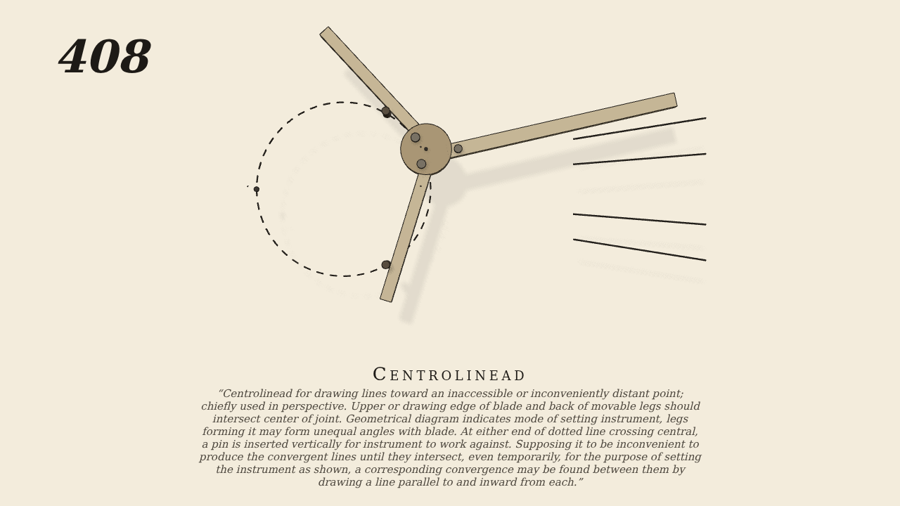
Centrolinead for drawing lines toward an inaccessible or inconveniently distant point; chiefly used in perspective. Upper or drawing edge of blade and back of movable legs should intersect center of joint. Geometrical diagram indicates mode of setting instrument, legs forming it may form unequal angles with blade. At either end of dotted line crossing central, a pin is inserted vertically for instrument to work against. Supposing it to be inconvenient to produce the convergent lines until they intersect, even temporarily, for the purpose of setting the instrument as shown, a corresponding convergence may be found between them by drawing a line parallel to and inward from each.
Only the input is driven; every other part of this model moves by physics (MuJoCo), and its ratios are measured. Run it live, change its parameters, or switch the friction off to see the output stop.
- Modelled as
- Brown's plan, the instrument lying on the drawing (no gravity): the blade with its upper (drawing) edge through the centre of the joint, and two legs clamped at 60 deg to the drawing edge produced, their backs also through the centre. Two pins stand in the board on the circle that passes through the distant point, 18 cm away on the drawing edge produced; the legs' backs bear on the pins (real contact). The hand presses the instrument towards the pins with a light spring and steadies it, and turns it 15 deg either way: that turning is the one driven joint, the instrument being otherwise free on the paper, so the pins alone guide it. Brown's geometrical diagram is drawn on the paper as the dotted circle, with lines already drawn towards the distant point. A light readout pivoted at the distant point and pinned at the instrument records the instrument's bearing from it and carries nothing.
- Measured
- As the hand turns the instrument the joint runs round the circle and the drawing edge always points at the distant point: the instrument's bearing from the distant point follows the blade's turning with slope 1.000 (r² 1.0000, check 1 ± 0.02). Penetration at the pins stays under 0.01 mm.
- Notes
- The joint's plate is a plain disc with the clamping screws, without Brown's curved slots; the legs are set at equal angles (Brown allows unequal); the diagram is drawn round the actual pins and distant point rather than as a separate figure.
Film (MP4) · Still (PNG) · Spec (YAML) · Model (MJCF)