An arrangement of parallel motion for side lever marine engines
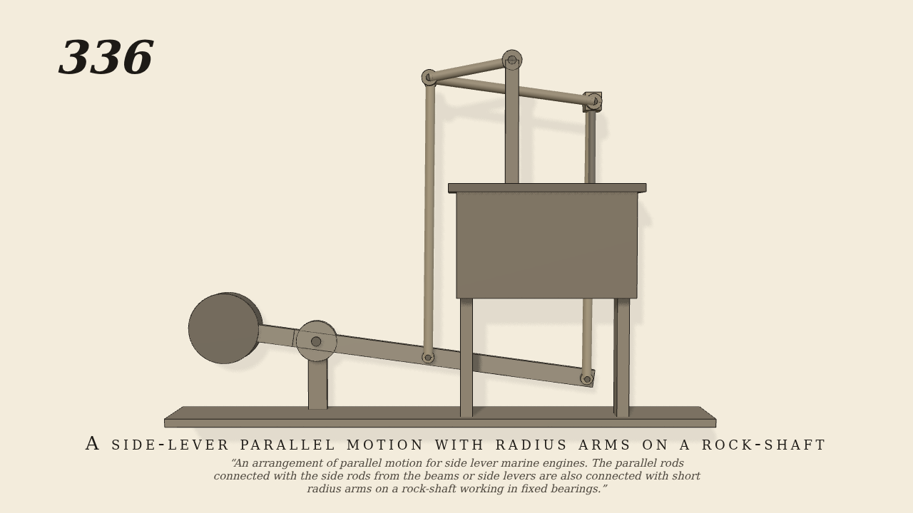
An arrangement of parallel motion for side lever marine engines. The parallel rods connected with the side rods from the beams or side levers are also connected with short radius arms on a rock-shaft working in fixed bearings.
Only the input is driven; every other part of this model moves by physics (MuJoCo), and its ratios are measured. Run it live, change its parameters, or switch the friction off to see the output stop.
- Modelled as
- The side lever rocks on A through 0.18 radian each way. Side rod B E rises 35 cm from the lever's end B, 35 cm from A, to cross-head E. A second rod rises the same height from M, 14.5 cm along the lever, to D. The parallel rod D E makes M D E B a parallelogram. A short radius arm on the rock-shaft F, which turns in a fixed bearing on the cylinder top, holds D. It lies level with D, and its length is AM squared over MB, 10.3 cm, which keeps D, and so E, on a straight line. Every joint is a pin in a ring with a few hundredths of a centimetre play. The cross-head is free to move up, down and across, and only the side rod and the parallel rod, through E's pin, place it. The lever is the only driven part.
- Measured
- The cross-head rises and falls 12.6 cm, 0.3485 m per radian of the lever, in step with it. The radius arm swings 1.42 times the lever's angle, the other way. E strays across by no more than 0.14 mm. The deepest contact is 0.005 mm.
- Notes
- Brown gives no sizes. The lever and rods follow the figure's proportions. The radius arm was set level with D and given the length that makes the motion straight; on paper E then keeps within 0.2 mm of its line. A weight on the lever's other arm stands in for the engine's other side. No steam is simulated.
Film (MP4) · Still (PNG) · Spec (YAML) · Model (MJCF)