A parallel motion used for the piston-rod of side lever marine engines
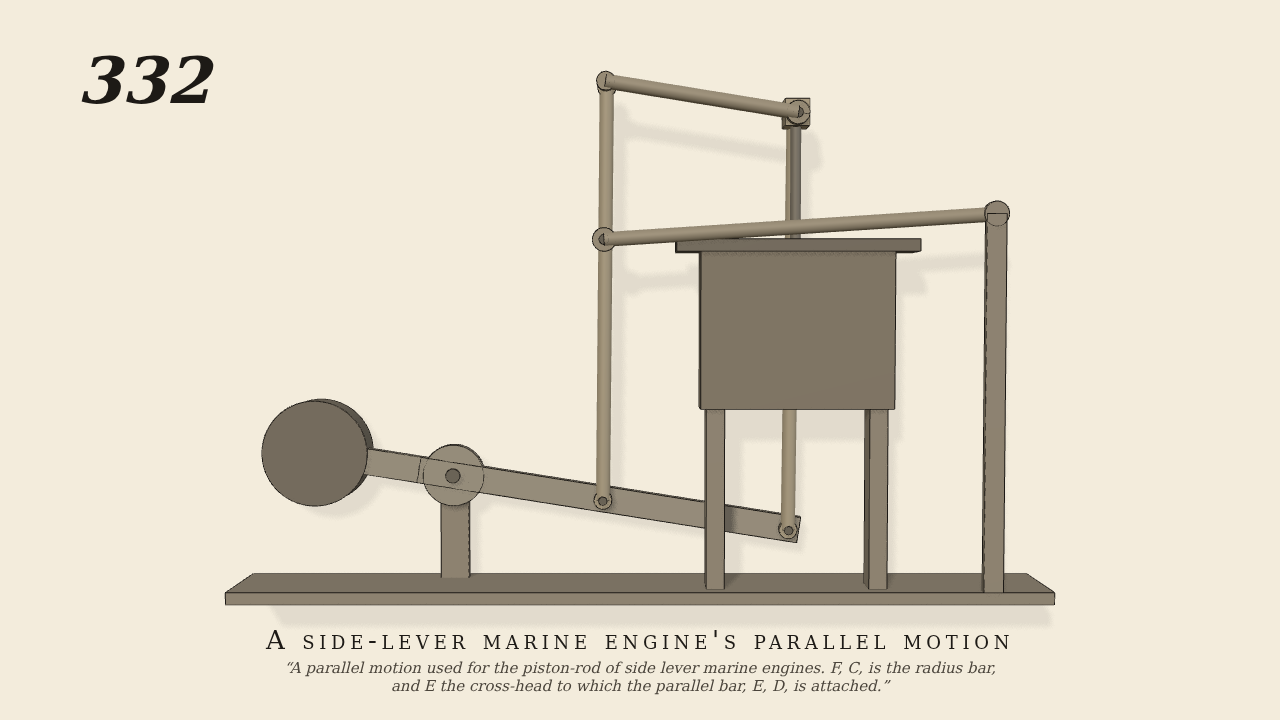
A parallel motion used for the piston-rod of side lever marine engines. F, C, is the radius bar, and E the cross-head to which the parallel bar, E, D, is attached.
Only the input is driven; every other part of this model moves by physics (MuJoCo), and its ratios are measured. Run it live, change its parameters, or switch the friction off to see the output stop.
- Modelled as
- The side lever rocks on A through 12 degrees each way, at a quarter of a cycle per second. It is 29 cm from A to its end B, and a short arm on the far side of A carries a weight in place of the engine's crank side. Side rod B E rises 35 cm to cross-head E. Rod M D rises from 13 cm along the lever and carries pin C 22 cm up. The parallel bar E D joins its top to E, so E, D, B and M make a parallelogram. Radius bar F C swings from F on the framing, 45 cm from A. Every joint is a pin in a ring with a few hundredths of a centimetre play. The cross-head slides freely up and down and sideways, and only the linkage holds it on its line. The lever is the only driven part.
- Measured
- Cross-head E rises and falls 12 cm, 0.288 m per radian of the lever, in step with it. The radius bar swings back at 0.404 of the lever's angle. E strays across by no more than 0.2 mm over the whole stroke. The deepest contact is 0.003 mm.
- Notes
- Brown gives no sizes. The lengths were chosen so the motion is close to straight. The C height and F position were found by a search; on paper they leave E within 0.01 mm of its line, and the rest comes from the play in the joints. The weight on the lever's other arm stands in for the engine's other side. Without it, the linkage's weight pulls the lever slowly down against the drive. No steam is simulated.
Film (MP4) · Still (PNG) · Spec (YAML) · Model (MJCF)