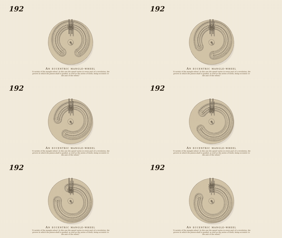
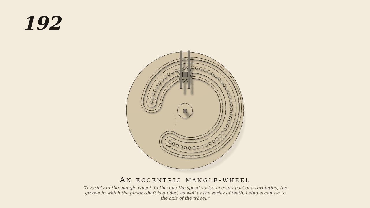
A variety of what is known as the “mangle-wheel.” One variety of…
A variety of what is known as the “mangle-wheel.” One variety of this was illustrated by 36. In this one the speed varies in every part of a revolution, the groove, b, d, in which the pinion-shaft is guided, as well as the series of teeth, being eccentric to the axis of the wheel.
Only the input is driven; every other part of this model moves by physics (MuJoCo), and its ratios are measured. Run it live, change its parameters, or switch the friction off to see the output stop.
- Modelled as
- No. 36 with its circle of 50 pins (radius 12) and its guiding groove made eccentric, their centre 2 from the wheel shaft. A 10-tooth pinion (pitch radius 2, driven 30 rpm one way) in a carriage sliding in the upright slot, its follower in the groove, rises and falls as the eccentric circle comes round; inside the pins it drives the wheel forward, round the end pin it passes outside and drives it back. A weight behind the face plate balances the eccentric pins and groove. gen192.py.
- Measured
- Inside: speed ratio slice means 0.145..0.182 (kinematic rp/(R+e)..rp/(R-e) = 0.143..0.200), mean 0.158; outside: -0.174..-0.142, mean -0.154; the carriage rises and falls 3.6-4.0 cm; penetration 0.12 mm. Pinion drive gain kv 1.5 (was 4) so the unloaded pinion is stable in the control.
- Notes
- Brown does not give the eccentricity; 2 cm (1/6 of the radius) is chosen.
Film (MP4) · GIF · Still (PNG) · Spec (YAML) · Model (MJCF)