Link-motion valve-gear of a locomotive
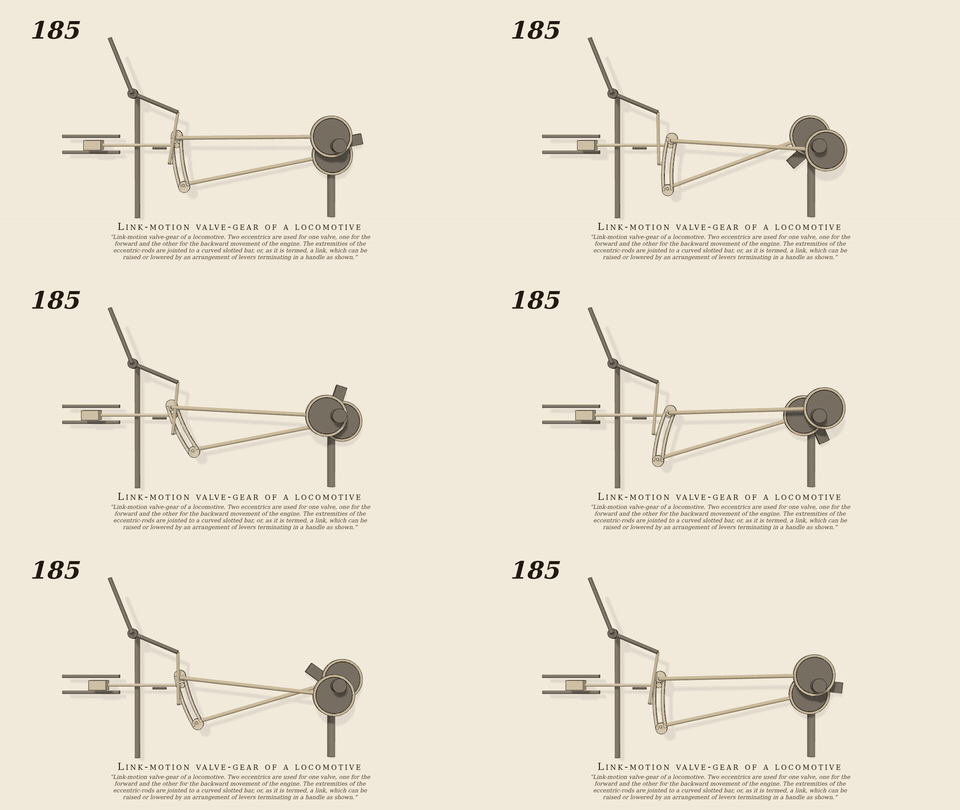
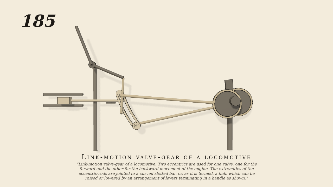
Link-motion valve-gear of a locomotive. Two eccentrics are used for one valve, one for the forward and the other for the backward movement of the engine. The extremities of the eccentric-rods are jointed to a curved slotted bar, or, as it is termed, a link, which can be raised or lowered by an arrangement of levers terminating in a handle as shown. In the slot of the link is a slide and pin connected with an arrangement of levers terminating at the valve-stem. The link, in moving with the action of the eccentrics, carries with it the slide, and thence motion is communicated to the valve. Suppose the link raised so that the slide is in the middle, then the link will oscillate on the pin of the slide, and consequently the valve will be at rest. If the link is moved so that the slide is at one of its extremities, the whole throw of the eccentric connected with that extremity will be given to it, and the valve and steam-ports will be opened to the full, and it will only be toward the end of the stroke that they will be totally shut, consequently the steam will have been admitted to the cylinder during almost the entire length of each stroke. But if the slide is between the middle and the extremity of the slot, as shown in the figure, it receives only a part of the throw of the eccentric, and the steam-ports will only be partially opened, and are quickly closed again, so that the admission of steam ceases some time before the termination of the stroke, and the steam is worked expansively. The nearer the slide is to the middle of the slot the greater will be the expansion, and vice versa.
Only the input is driven; every other part of this model moves by physics (MuJoCo), and its ratios are measured. Run it live, change its parameters, or switch the friction off to see the output stop.
- Modelled as
- Stephenson link motion. The crank-shaft (the only driven joint, 30 rpm) carries two eccentrics of throw 3, set 110 deg and -110 deg from the crank (advance 20 deg). Their 45 cm rods are jointed to the ends of the link, a slot curved to radius 45 about the shaft with 14 between the pins. The link hangs by a saddle pin from a 15 cm hanger on the 14 cm lifting arm of the weigh-shaft, which carries the reversing handle. The die on the end of the valve rod runs in the slot by real contact; the rod slides level to the slide valve in the steam chest (the plates rocker is left out). The hand sets the handle with a joint spring: full forward gear (die 5 from the middle) at the start, mid gear at 6.5 s, full backward gear at 14.5 s. Expected valve curves come from a kinematic solution of the linkage in gen185.py.
- Measured
- Valve half-travel forward 2.51 cm (kinematic 2.47), mid 1.52 (1.48), backward 2.41 (2.37); the sim follows the kinematic curves to 0.4 mm rms in all three gears. Over a quarter turn about crank dead centre the valve moves -0.0219 m/rad in forward gear (kinematic -0.0205) and +0.0180 in backward (0.0202): the motion reverses. Penetration 0.01 mm.
- Notes
- In mid gear the valve still moves by the lap and lead (the eccentrics advance 20 deg), not at rest as Brown says. The crank runs up to 0.1 rad behind time by 18 s, which tilts the follow slopes; tol 15%.
Film (MP4) · GIF · Still (PNG) · Spec (YAML) · Model (MJCF)