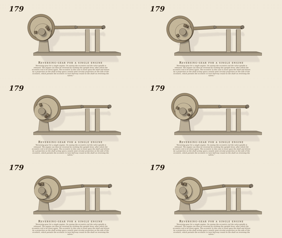
Reversing-gear for a single engine
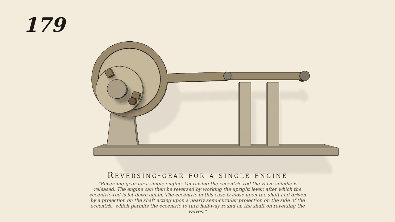
Reversing-gear for a single engine. On raising the eccentric-rod the valve-spindle is released. The engine can then be reversed by working the upright lever, after which the eccentric-rod is let down again. The eccentric in this case is loose upon the shaft and driven by a projection on the shaft acting upon a nearly semi-circular projection on the side of the eccentric, which permits the eccentric to turn half-way round on the shaft on reversing the valves.
Only the input is driven; every other part of this model moves by physics (MuJoCo), and its ratios are measured. Run it live, change its parameters, or switch the friction off to see the output stop.
- Modelled as
- The shaft (the one driven joint) turns 2 turns forward and then 4 back, as a swing of +-2 turns in 12.5 s. A 2 cm eccentric is loose on it; a lug on the shaft rides in a recess in the eccentric that spans half a turn between two stops (real contact). A 14 cm eccentric rod through the strap works a valve spindle on a slide. The eccentric is damped so that it stops when the lug leaves it. No gravity. gen179.py.
- Measured
- Going forward the eccentric turns with the shaft (j_e/j_s 1.0000), the spindle follows the shaft at -0.0198 m/rad (kinematic -0.020). After the shaft reverses it runs half a turn through the recess, then picks up the other stop: the eccentric again follows 1.0000, and the spindle now follows at +0.0191 / +0.0193 / +0.0197 / +0.0202 m/rad at the same shaft angles where it was -0.0198 / +0.020 going forward, i.e. the valve motion has reversed in phase. Stroke 4.0 cm.
- Notes
- Reading of the figure: the upright lever, the hook releasing the valve spindle and raising of the eccentric rod are not modelled; the shaft is turned by a swing schedule rather than an engine. The damping on the eccentric stands in for the rod and valve load.
Film (MP4) · GIF · Still (PNG) · Spec (YAML) · Model (MJCF)