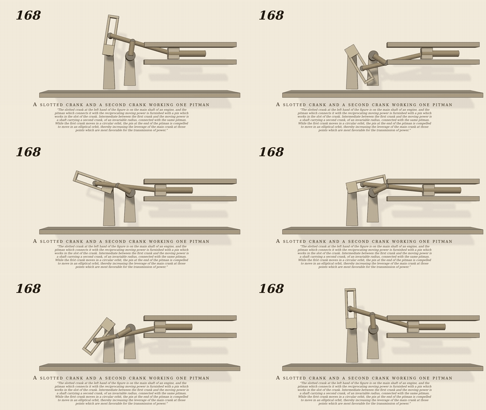
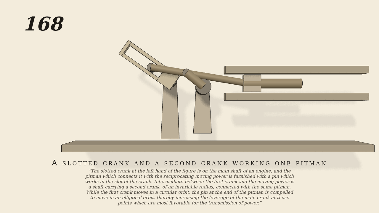
The slotted crank at the left hand of the figure is on the main…
The slotted crank at the left hand of the figure is on the main shaft of an engine, and the pitman which connects it with the reciprocating moving power is furnished with a pin which works in the slot of the crank. Intermediate between the first crank and the moving power is a shaft carrying a second crank, of an invariable radius, connected with the same pitman. While the first crank moves in a circular orbit, the pin at the end of the pitman is compelled to move in an elliptical orbit, thereby increasing the leverage of the main crank at those points which are most favorable for the transmission of power.
Only the input is driven; every other part of this model moves by physics (MuJoCo), and its ratios are measured. Run it live, change its parameters, or switch the friction off to see the output stop.
- Modelled as
- The main crank (the one driven joint, 20 rpm) is slotted; the pitman carries a pin that runs in the slot by real contact. The pitman is also carried by a second crank of invariable radius (3.1 cm) on its own shaft 5 cm away, and its far end works the reciprocating moving power, a slide in guides. The pin is compelled to an elliptical orbit. No gravity (a plan). gen168.py.
- Measured
- The slide follows the main crank at -0.0620 and +0.0298 m/rad (r2 at least 0.994); the second crank at +1.975 and +1.039 rad/rad (r2 at least 0.998), one turn per turn. The slot works from 2.7 to 6.2 cm radius, the slide goes 6.2 cm, penetration 0.10 mm.
- Notes
- The pin in the slot is real contact, no link. Dimensions were found by a search for a pair that clears every dead point. The driver is a soft servo (kv 2) so that the crank still turns at speed when its slot is switched off in the control.
Film (MP4) · GIF · Still (PNG) · Spec (YAML) · Model (MJCF)