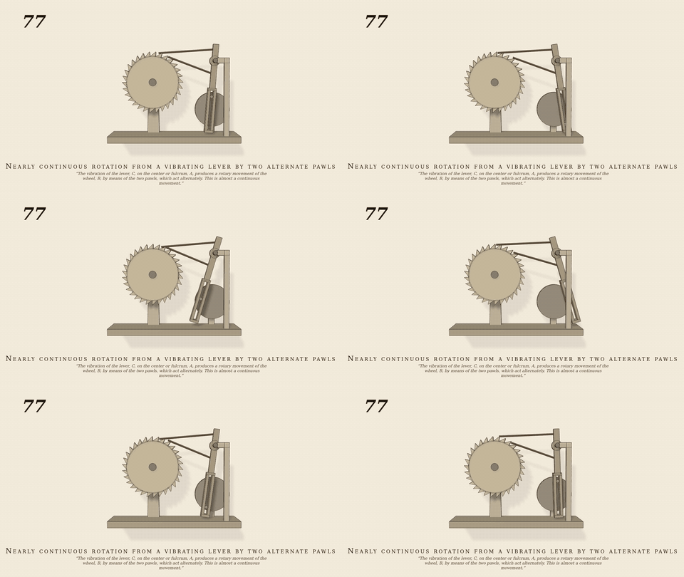
The vibration of the lever, C, on the center or fulcrum, A,…
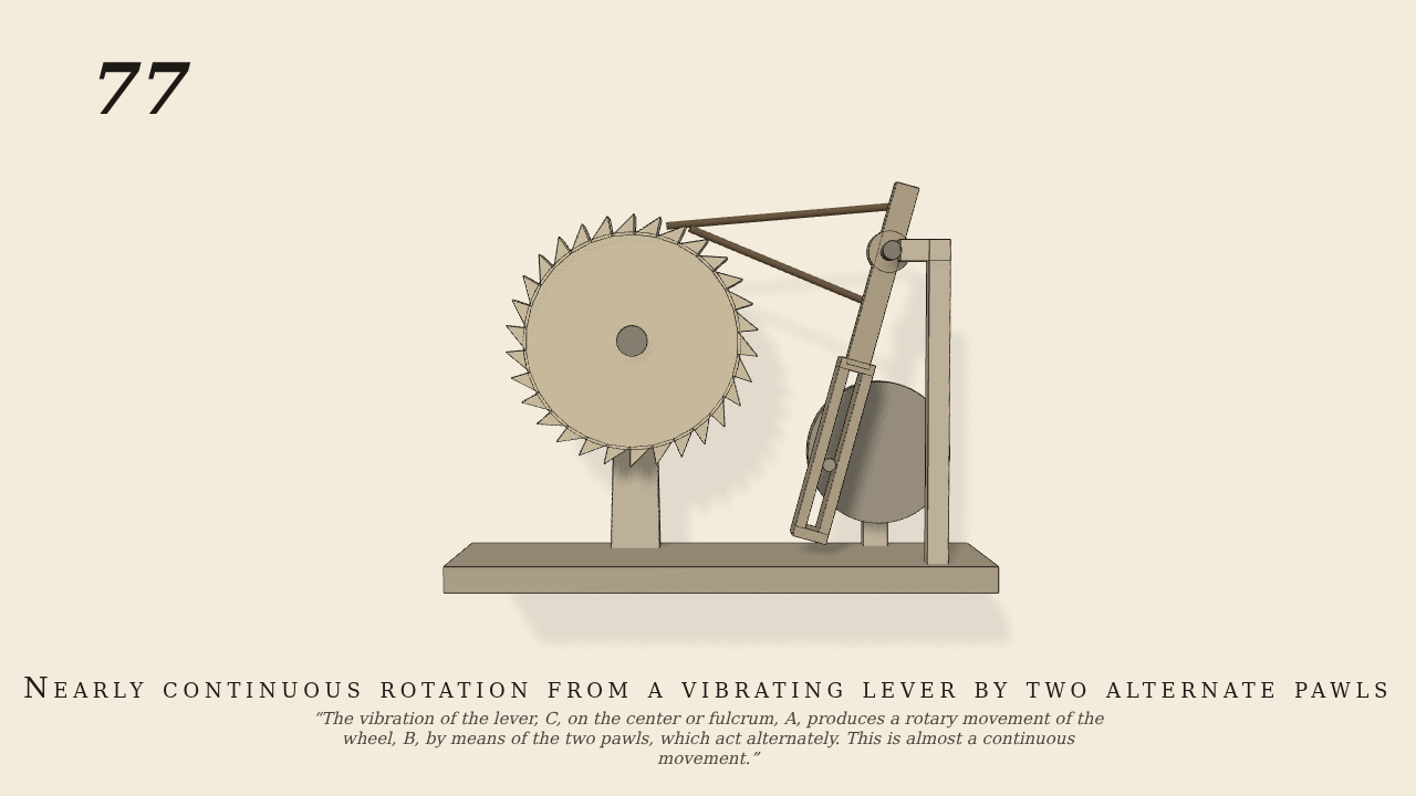
The vibration of the lever, C, on the center or fulcrum, A, produces a rotary movement of the wheel, B, by means of the two pawls, which act alternately. This is almost a continuous movement.
Only the input is driven; every other part of this model moves by physics (MuJoCo), and its ratios are measured. Run it live, change its parameters, or switch the friction off to see the output stop.
- Modelled as
- Upright lever C on fulcrum A, to the right of the 30-tooth ratchet-wheel B, as in the plate. A crank (the only driven joint, 30 rpm) works a pin in a slot at C's lower end, so C swings about 0.28 rad each way. Two pawls are pinned on C, 2.04 cm above and 2.04 cm below A, and lie by their weight on B's teeth at the upper right, each leaning 15 deg in from B's tangent. The pins move in opposite directions, so one pawl pushes a tooth while the other slides back, and the pawls change places every stroke. B is held by bearing friction.
- Measured
- Ratio B/crank, 3 to 13 s: 0.06665 vs 2/30, -0.03%. One tooth each stroke, so B moves on both strokes. Max penetration under 1 mm.
- Notes
- The plate shows a pin-wheel with hooked rods. Here the pawls are plain capsules on saw teeth (same action). Pawl joint ranges have to be wider than the lever swing; with a 0.2 rad stop the stops took the push. The slot cheeks must clear B's teeth (the lever is 10 cm off B's centre).
Film (MP4) · GIF · Still (PNG) · Spec (YAML) · Model (MJCF)