The vertical shaft is made to drive the horizontal one in either direction
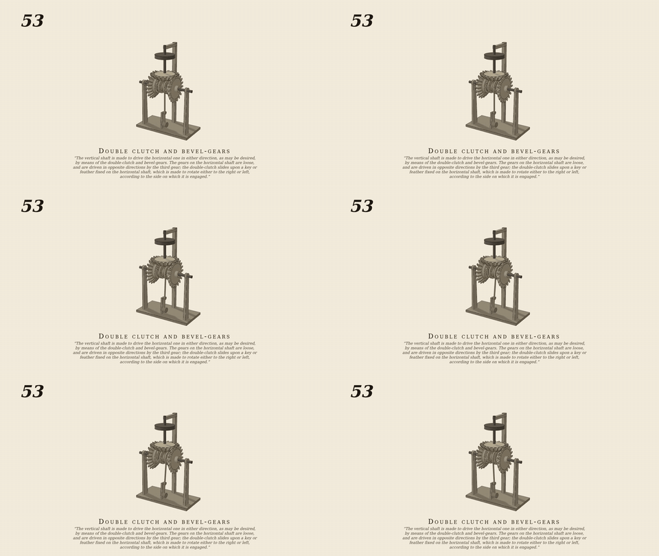
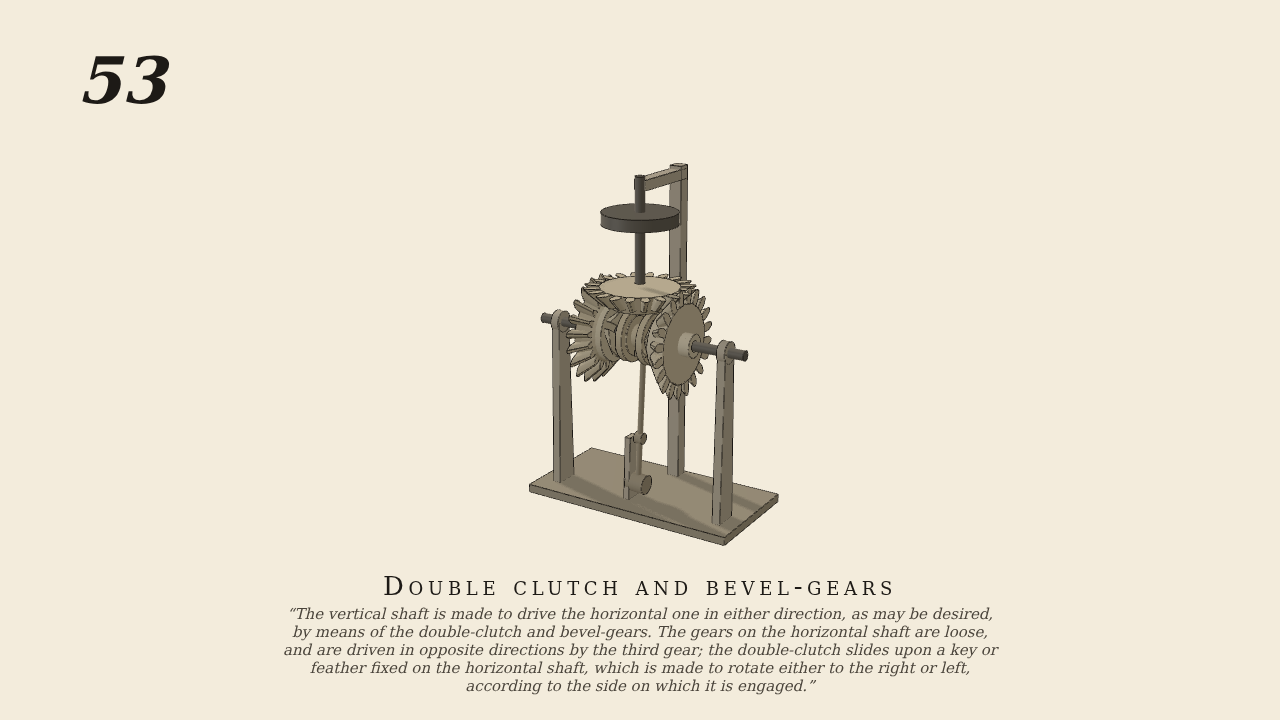
The vertical shaft is made to drive the horizontal one in either direction, as may be desired, by means of the double-clutch and bevel-gears. The gears on the horizontal shaft are loose, and are driven in opposite directions by the third gear; the double-clutch slides upon a key or feather fixed on the horizontal shaft, which is made to rotate either to the right or left, according to the side on which it is engaged.
Only the input is driven; every other part of this model moves by physics (MuJoCo), and its ratios are measured. Run it live, change its parameters, or switch the friction off to see the output stop.
- Modelled as
- Brown's figure 53: the upright shaft's bevel (driven, with its pulley) meshes two miter bevels loose on the horizontal shaft, which turn opposite ways; each carries slotted jaws on its inner face; the double clutch slides on the shaft's feather between them with round jaws on both faces; the hand lever throws it over to A at 2 s, across to B at 5.5 s, back to the middle at 9 s
- Measured
- A/up −0.9997, B/up 0.9997; shaft/up 0.0000 in the middle, −1.0018 engaged with A, 0.9992 with B, 0.0010 back in the middle; max penetration 0.03 mm; also passes at 25 rpm (at 10 rpm B's slots come round after the window opens: 0.41 there)
- Notes
- No. 48's capsule jaws in slotted lofts, mirrored for A; bevels on parts (No. 49). PGS solver: CG and Newton blow up (NaN in one step from calm) on the bevel-and-jaw contacts. batch7/gen053.py. Negative control: clutch jaws out of contact → the shaft stands (−0.0007).
Film (MP4) · GIF · Still (PNG) · Spec (YAML) · Model (MJCF)