Mangle-wheel and pinion
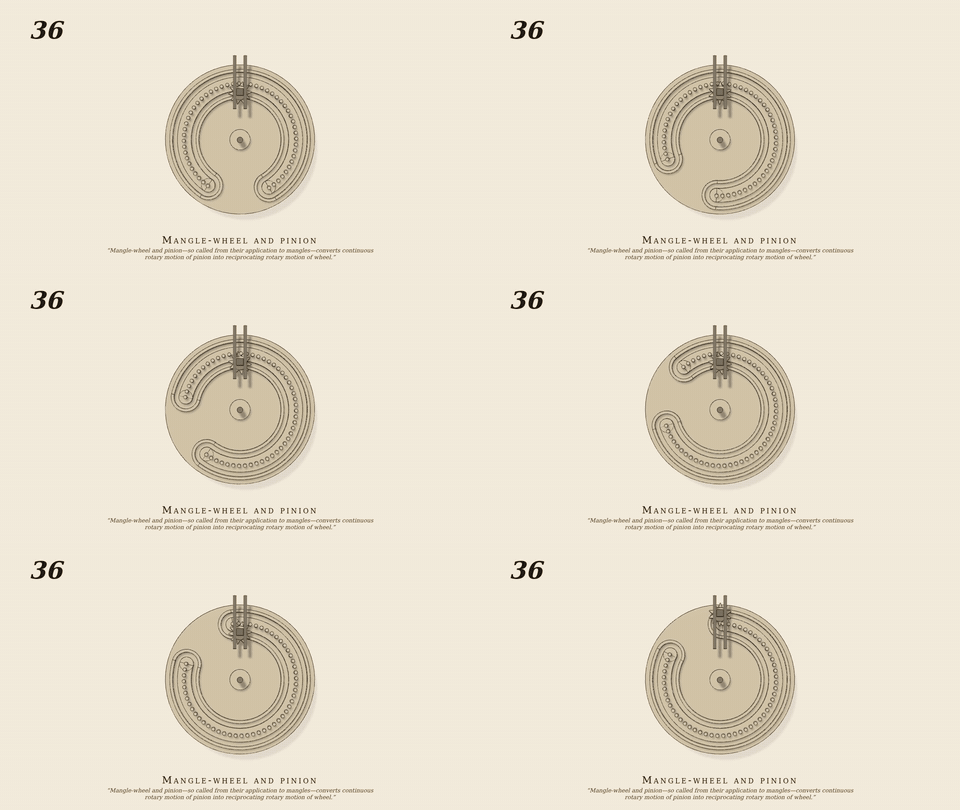
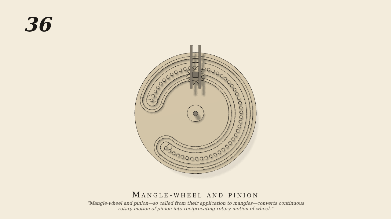
Mangle-wheel and pinion—so called from their application to mangles—converts continuous rotary motion of pinion into reciprocating rotary motion of wheel. The shaft of pinion has a vibratory motion, and works in a straight slot cut in the upright stationary bar to allow the pinion to rise and fall and work inside and outside of the gearing of the wheel. The slot cut in the face of the mangle-wheel and following its outline is to receive and guide the pinion-shaft and keep the pinion in gear.
Only the input is driven; every other part of this model moves by physics (MuJoCo), and its ratios are measured. Run it live, change its parameters, or switch the friction off to see the output stop.
- Modelled as
- 50 pins (r 0.35) on a circle of radius 12 over 294 deg on the wheel's face; behind them a groove: a track inside the pins, one outside, half-rounds about the end pins; a 10-tooth pinion (r 2) in a carriage sliding in a stationary upright slot, its follower in the groove
- Measured
- ω_wheel/ω_pinion = +0.1681 inside the pins, -0.1666 outside (±2/12 = 0.1667), reversing at each end pin
- Notes
- Only the pinion is motor-driven (30 rpm, one way); the groove carries it round the end pin and the carriage rises 4 cm. Negative control: pins out of contact → the wheel stands (0.0000 rad vs 2.03 driven, 4 s).
Film (MP4) · GIF · Still (PNG) · Spec (YAML) · Model (MJCF)