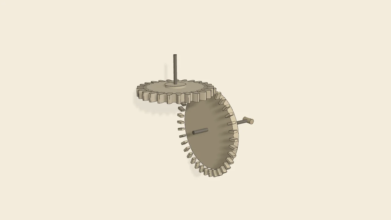
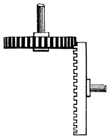
Crown-wheel and spur-gear
The wheel to the right is termed a “crown-wheel;” that gearing with it is a spur-gear. These wheels are not much used, and are only available for light work, as the teeth of the crown-wheel must necessarily be thin.
Only the input is driven; every other part of this model moves by physics (MuJoCo), and its ratios are measured. Run it live, change its parameters, or switch the friction off to see the output stop.
- Modelled as
- a crown wheel (36 thin fins, 0.42 cm wide to the azimuth, standing 0.8 cm out of one face, band radius 9.36 cm at a 0.52 cm module) on a horizontal shaft, meshed by a 25-tooth involute pinion (the No. 24 gear, same module) on a vertical shaft at right angles; only the pinion is motor-driven, the crown turns by fin strikes alone
- Measured
- omega_crown/omega_pinion = 0.6944 (expect 25/36 = 0.6944), tooth penetration ≤ 0.1 mm; the fins are flat-sided, as drawn, so the crown runs with a ±3.5 % ripple at the tooth rate (20 ms means)
- Notes
- Gears are phased half a tooth over so the teeth start clear of the fins; solver PGS (Newton/CG are not stable through the skew strikes). Negative control: the fins' contact off → the crown stays still (0.000 rad/s) while the pinion free-runs at 2.83 rad/s.
Film (MP4) · Still (WebP) · Spec (YAML) · Model (MJCF)