Bevel-gears
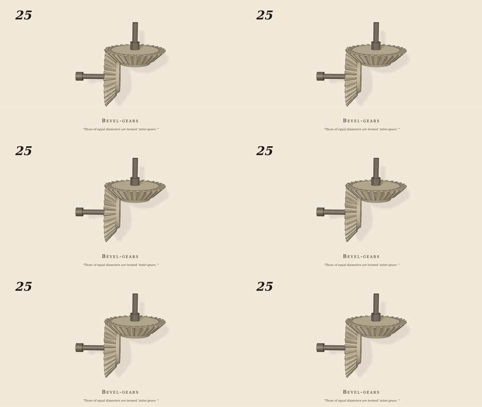
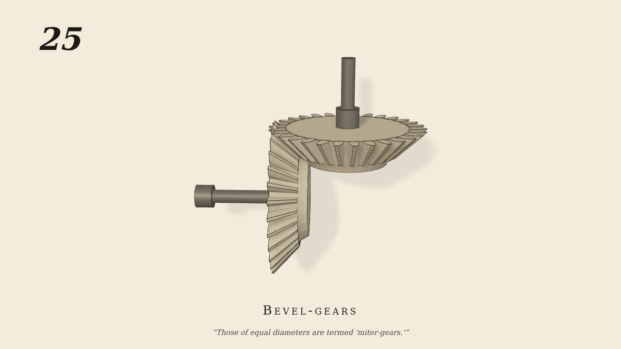
Bevel-gears. Those of equal diameters are termed “miter-gears.”
Only the input is driven; every other part of this model moves by physics (MuJoCo), and its ratios are measured. Run it live, change its parameters, or switch the friction off to see the output stop.
- Modelled as
- two 30-tooth miter gears (45 deg cones), each keyed to its own shafting at 90 deg (upright shaft up, lay shaft to the left), pitch cones meeting at a common apex; teeth mesh through per-tooth convex hulls
- Measured
- ω_lay/ω_up +0.9999 (z30/z30 = 1), pen ≤ 0.014 mm
- Notes
- Only the upright shaft is motor-driven (30 rpm); the lay shaft turns solely through bevel tooth contact, same sense (both axes right-handed at 90 deg). Both gears at phase 0, which meshes them tooth into space at the start (the half pitch of No. 7's train started the teeth 5.2 mm into each other). Negative control: the tooth contact switched off → the lay shaft is still (0.0000 while the driver runs).
Film (MP4) · GIF · Still (PNG) · Spec (YAML) · Model (MJCF)