“Grasshopper” beam engine
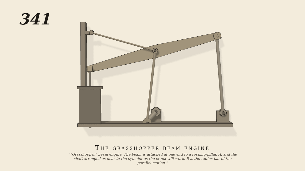
“Grasshopper” beam engine. The beam is attached at one end to a rocking-pillar, A, and the shaft arranged as near to the cylinder as the crank will work. B is the radius-bar of the parallel motion.
Only the input is driven; every other part of this model moves by physics (MuJoCo), and its ratios are measured. Run it live, change its parameters, or switch the friction off to see the output stop.
- Modelled as
- Seen from the side, as Brown, gravity on, proportions from the figure at half scale. The beam is carried at its outer end on the top of the rocking pillar A, whose foot turns on a footstep; the radius-bar B, centred on the wall, holds the beam near its piston end; the piston-rod's cross-head hangs from the beam's end pin and slides in the cylinder's line, free also to move across it; the connecting-rod drops from the beam to a 5 cm crank on the shaft beside the cylinder. Every joint is a real pin. Only the crank's shaft is driven (15 rpm).
- Measured
- The crank rocks the beam on its pillar, and the radius-bar and the swinging pillar together guide the beam's end in a nearly straight line: the cross-head travels the cylinder's line through a stroke of about 20 cm (half-stroke 0.102 m) while straying across it by no more than 0.3 mm, though it is free to move 1 cm either way.
- Notes
- The radius-bar's length and the piston end of the beam are re-proportioned slightly from the figure so that the parallel motion runs straight (on the figure's own proportions the cross-head strays about 5 cm); all joints are pins (no ring-and-pin contact).
Film (MP4) · Still (PNG) · Spec (YAML) · Model (MJCF)