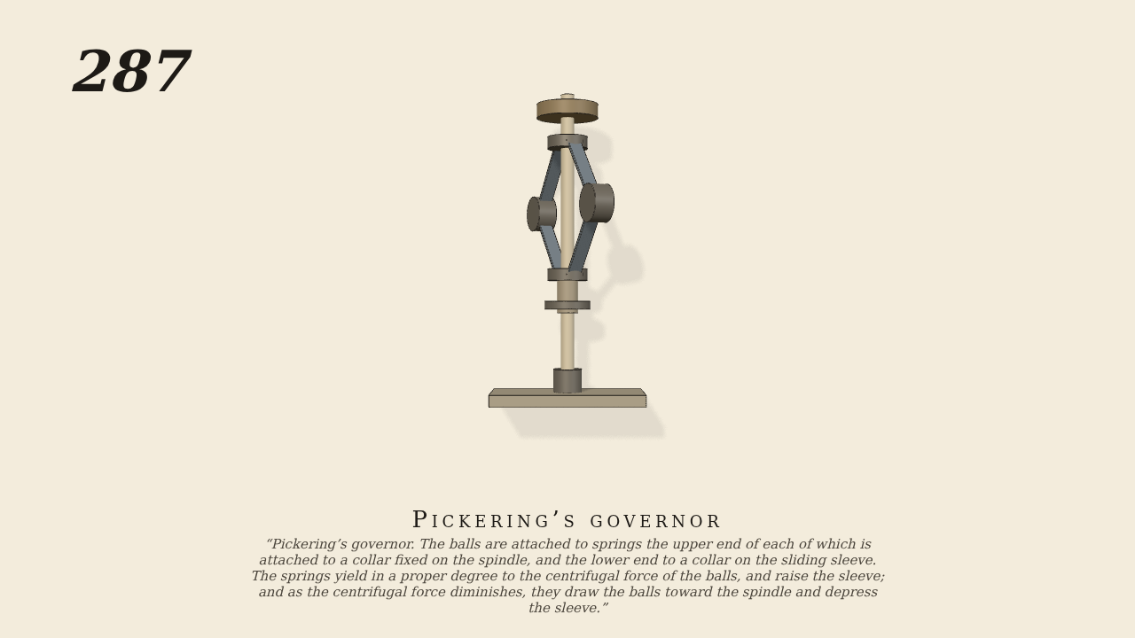
Pickering’s governor
Pickering’s governor. The balls are attached to springs the upper end of each of which is attached to a collar fixed on the spindle, and the lower end to a collar on the sliding sleeve. The springs yield in a proper degree to the centrifugal force of the balls, and raise the sleeve; and as the centrifugal force diminishes, they draw the balls toward the spindle and depress the sleeve.
Only the input is driven; every other part of this model moves by physics (MuJoCo), and its ratios are measured. Run it live, change its parameters, or switch the friction off to see the output stop.
- Modelled as
- The spindle is the one driven joint, at 150 turns a minute. Each spring is a flat steel strip. Its upper end is hinged on a collar fixed at the top of the spindle, and its lower end on the collar of a sleeve that slides on the spindle. The ball (0.5 kg) is fast on the middle of the strip. Each strip is modelled as two 9 cm halves, with its bending stiffness in the joints at the ends and at the ball. Their free set holds the balls and the 0.3 kg sleeve where they start, at rest under gravity. The sleeve is joined to the strips by pins only. As the spindle runs, the balls fly out against the springs, the strips bow, and their ends draw together, lifting the sleeve.
- Measured
- As the balls first fly out the sleeve rises 0.0889 m per radian of the strip's upper half (0.0849 by the strips' geometry over the swing, r² 0.991). Both sides move alike (1.0000). The strips stand 0.394 rad past the start, where spin, springs and weight balance at 0.387 rad by hand. The sleeve stands 3.36 cm up (3.28 by hand).
- Notes
- Brown gives no sizes or speeds. A real strip bends along its whole length; here it bends only at three joints. There is no contact in this movement: the strips and the sleeve are joined by pins, as in No. 161.
Film (MP4) · Still (PNG) · Spec (YAML) · Model (MJCF)