Valve motion and reversing gear used in oscillating marine engines
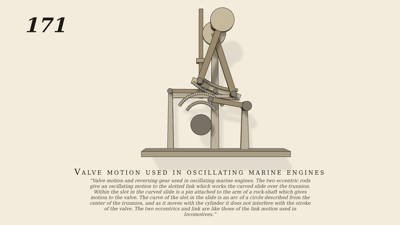
Valve motion and reversing gear used in oscillating marine engines. The two eccentric rods give an oscillating motion to the slotted link which works the curved slide over the trunnion. Within the slot in the curved slide is a pin attached to the arm of a rock-shaft which gives motion to the valve. The curve of the slot in the slide is an arc of a circle described from the center of the trunnion, and as it moves with the cylinder it does not interfere with the stroke of the valve. The two eccentrics and link are like those of the link motion used in locomotives.
Only the input is driven; every other part of this model moves by physics (MuJoCo), and its ratios are measured. Run it live, change its parameters, or switch the friction off to see the output stop.
- Modelled as
- The shaft (the one driven joint, 20 rpm) carries two eccentrics (1.4 cm throw, 110 degrees ahead of and behind the crank) whose 12 cm rods join the ends of a slotted link (6.8 cm between pins, slot an arc of 12 cm radius), held by a 9 cm radius rod. The valve rod's pin runs in the link slot 2.8 cm off centre; the rod carries a curved slide over the trunnion, in whose slot runs the pin of a rock-shaft arm. No gravity. gen171.py.
- Measured
- The valve rod strokes 2.6 cm and follows the shaft at -0.0099 / +0.0116 / -0.0116 m/rad; the rock-shaft arm turns 22 degrees in all (+0.165 / -0.167 / +0.153 rad/rad, window r2 above 0.99); the link swings 24 degrees each way. Penetration 0.
- Notes
- Reading of the figure: the link is hung by a radius rod and the die-block pin is a rod in the slot; the cylinder (which oscillates in the original) is left fixed, so the slide's arc stays about the trunnion. The radius rod must be roughly at right angles to the eccentric rods, otherwise the link is not located sideways.
Film (MP4) · GIF · Still (PNG) · Spec (YAML) · Model (MJCF)