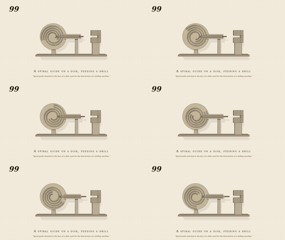
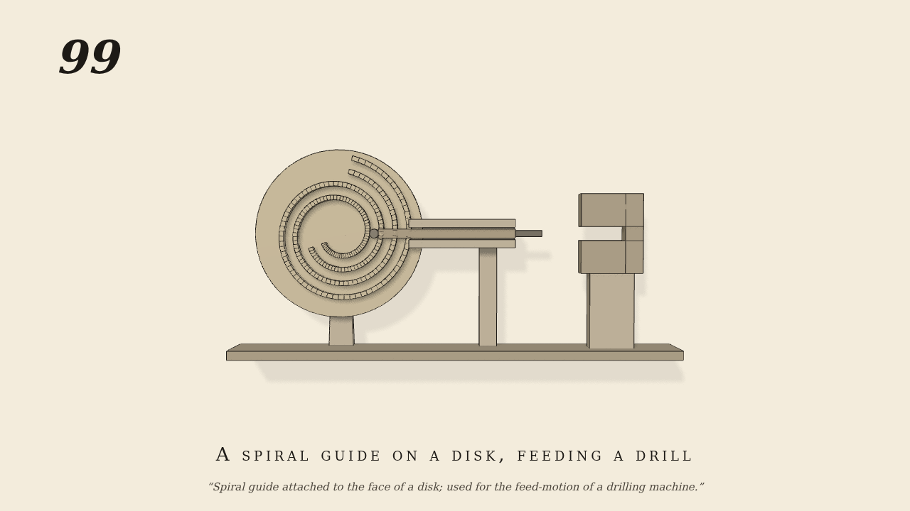
Spiral guide attached to the face of a disk
Spiral guide attached to the face of a disk; used for the feed-motion of a drilling machine.
Only the input is driven; every other part of this model moves by physics (MuJoCo), and its ratios are measured. Run it live, change its parameters, or switch the friction off to see the output stop.
- Modelled as
- A disk (8 rpm, the only driven joint) has a spiral groove cut in its face: 1.06 cm wide, its centre line starting 3 cm out and opening 0.5 cm to the radian over 1.6 turns. The drill-spindle slide carries a pin that works in the groove by real contact (0.03 cm clear each side), so each turn of the disk feeds the drill 3.14 cm on, steadily, towards the work (a block with a blind hole).
- Measured
- Drill feed against the disk: 0.0050 and 0.0050 m/rad (ideal 0.005 = the spiral rise), r2 0.9998-0.9999 in two windows; feed 0.18..4.35 cm over the run (4.9 cm allowed); max penetration 0.01 mm.
- Notes
- The groove walls are 115 flat quads a side (sagitta under 0.1 mm); the slide damping (1.0) stands for the cut.
Film (MP4) · GIF · Still (PNG) · Spec (YAML) · Model (MJCF)