Pulley Transmission
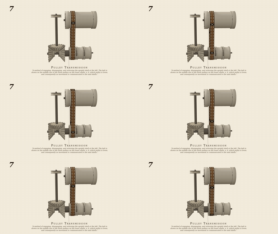
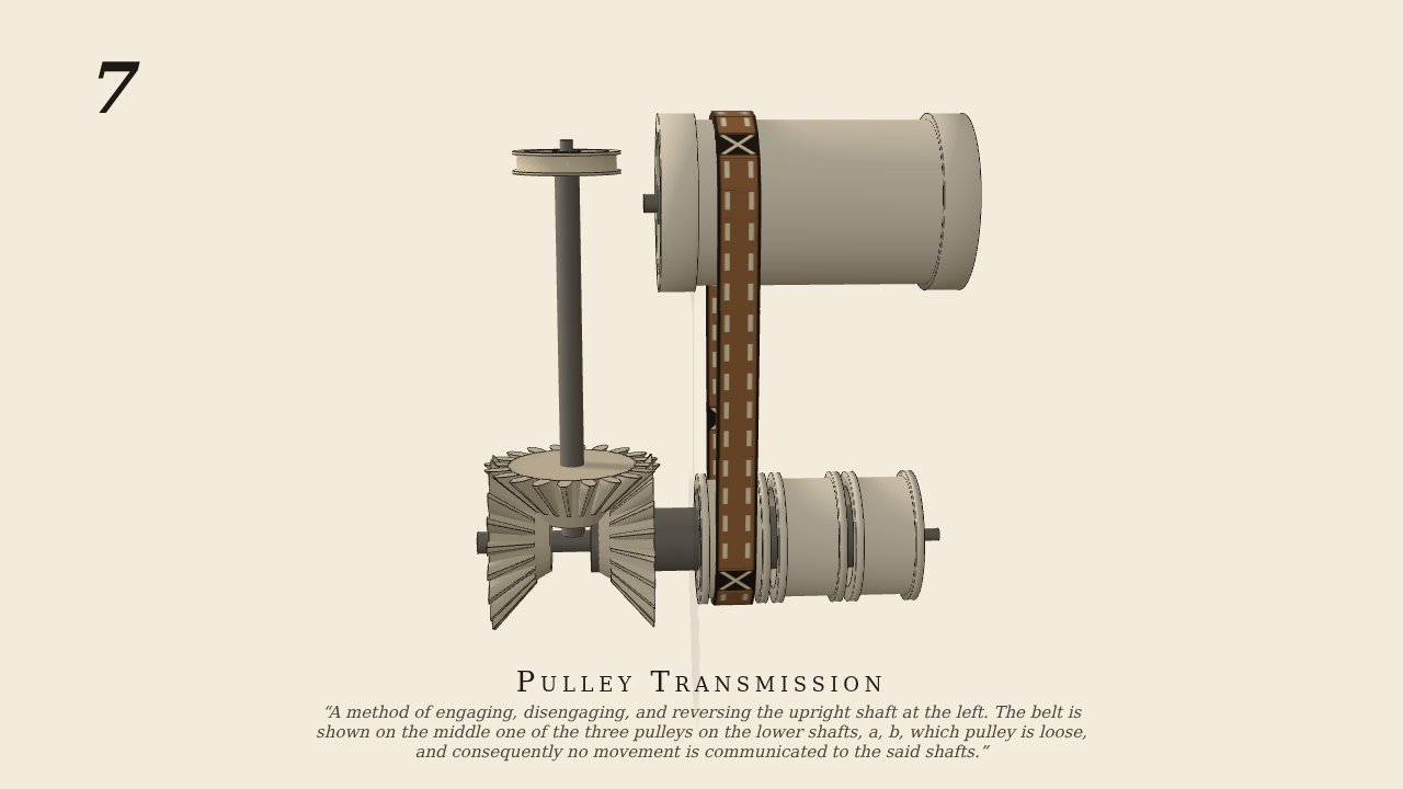
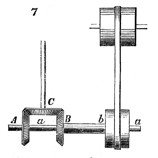
A method of engaging, disengaging, and reversing the upright shaft at the left. The belt is shown on the middle one of the three pulleys on the lower shafts, a, b, which pulley is loose, and consequently no movement is communicated to the said shafts. When the belt is traversed on the left-hand pulley, which is fast on the hollow shaft, b, carrying the bevel-gear, B, motion is communicated in one direction to the upright shaft; and on its being traversed on to the right-hand pulley, motion is transmitted through the gear, A, fast on the shaft, a, which runs inside of b, and the direction of the upright shaft is reversed.
Only the input is driven; every other part of this model moves by physics (MuJoCo), and its ratios are measured. Run it live, change its parameters, or switch the friction off to see the output stop.
- Modelled as
- belt (friction; 40-link steel band, 40 N) + 3 straight bevels (per-tooth convex hulls) on concentric shafts a/b, loose middle pulley
- Measured
- band on b → ω_up/ω_drum −1.306, band on a → +1.297 (reversed), band on loose pulley → 0.000; μ≈0 control 0.000; teeth out of contact → upright 0.000; belt dev 0.17, pen 0.37 mm
- Notes
- Only the drum is motor-driven. Belt position is a passive variant (all three tested); the render shows it on b's pulley so it runs.
Film (MP4) · GIF · Still (PNG) · Spec (YAML) · Model (MJCF)